Maurizio Baldinucci
Some time ago, during one of my usual explorations of various websites and social media pages dedicated to the history of diving equipment, I noted some images of a display case belonging to the exhibition of a well-known French collector. This collector is specialized in collecting historic equipment produced exclusively by the company La Spirotechnique. The history and evolution of this equipment produced by the French company are showcased on his dedicated website www.spiro-vintage.com. The site is beautiful, constantly updated, and full of photos and information of great value to enthusiasts and collectors. His collection includes very rare and unique samples, including several Cousteau-Gagnan CG-45 regulators. The great fame of this device, linked to the fact that it is considered the first modern automatic and self-contained breathing apparatus, makes these collections true treasures to be valued and preserved.
Within this display case packed with CG-45s produced in various configurations depending on the year of manufacture and model, I recognized the second stage of what was the initial prototype of the CG-45 regulator (see Fig. 1 and Fig. 2). This prototype, which underwent several modifications and improvements from 1943 to 1945 until reaching the production configuration, is commonly identified as the CG-43.
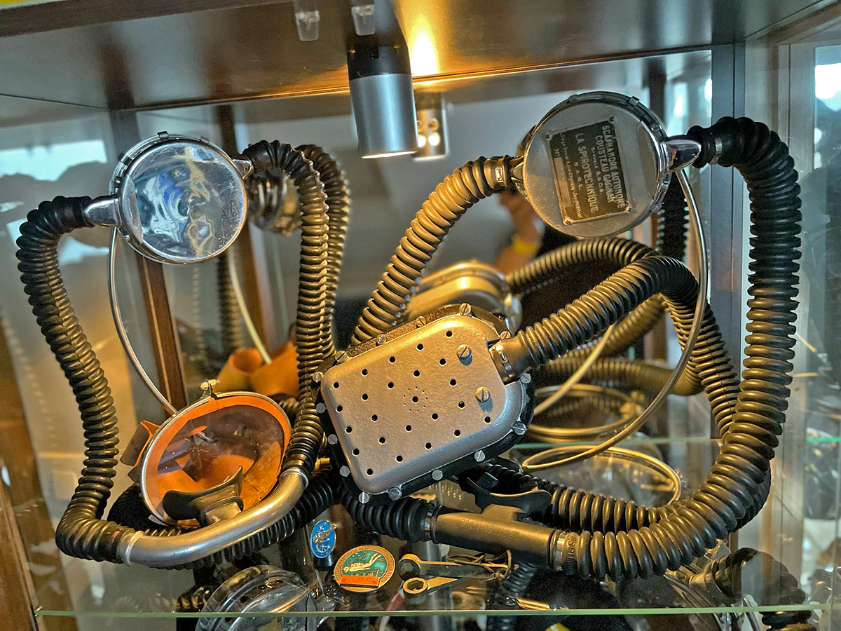
fig. 1 |
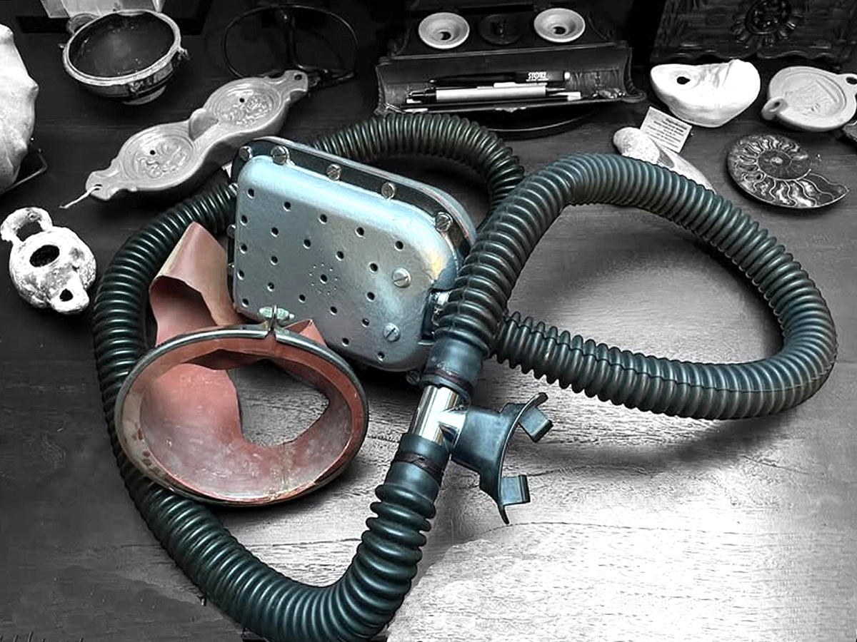
fig. 2 |
This stimulated my curiosity, so I decided to contact this collector for further details. I discovered that the unit in his display case was not an original prototype of the CG-43, but only a partial reconstruction. My contact was generous in providing me with a wealth of information that allowed me to fully put together the various stages of this device's evolution.
And this is how we arrived at his incomplete display sample.
One of the prototypes of the Cousteau-Gagnan scuba set (the only one still existing as far as is known to date) had been found inside a wooden box donated to the Frédéric Dumas Museum in Sanary-sur-Mer, a town on the French coast near Marseille. It is told that Cousteau himself delivered this box of equipment to Robert Buffaz, a well-known diving pioneer and French spearfishing champion, before the rest of his diving equipment was destroyed in a warehouse fire in Marseille (supposedly in 1944).
The Sanary-sur-Mer Museum was founded in 1974 to preserve the memory of Frédéric Dumas (1913–1991), one of the pioneers of SCUBA diving who, along with Jacques-Yves Cousteau and Philippe Tailliez, formed the trio of pioneers known as "Les Mousquemers" (a French nickname that probably translates to "The Musketeers of the Sea") (see Fig. 3). The story and adventures of this man, who made a fundamental contribution to Cousteau's exploits and successes and who spent most of his life in Sanary-sur-Mer, are told by Franck Machu in his biographical book "Frédéric Dumas - Fils de Poseidon" (see Fig. 4).
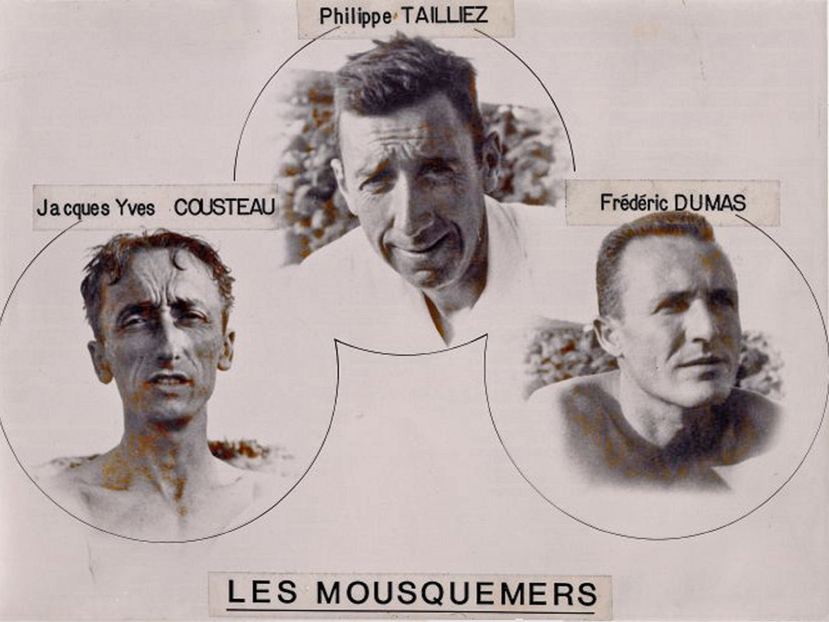
fig. 3 |
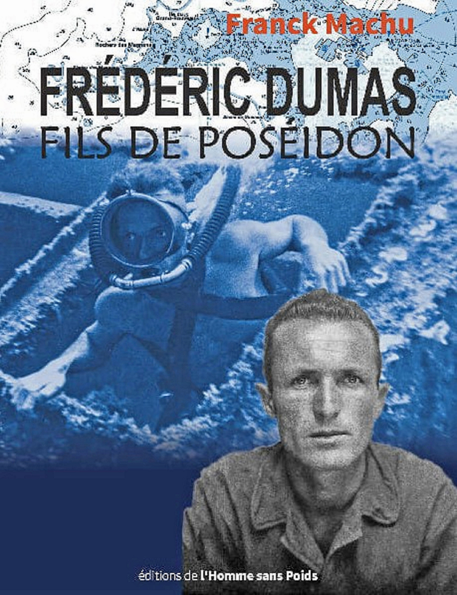
fig. 4 |
The museum, in addition to exhibiting the early underwater hunting and diving gear used by Dumas, also contains several other equipment used from the late 1930s to the 1960s (see Fig. 5 and Fig. 6).
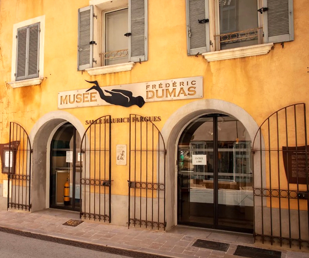
fig. 5 |
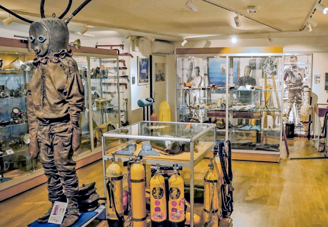
fig. 6 |
The box donated to the museum by Robert Buffaz's family contained the material shown in Fig. 7.
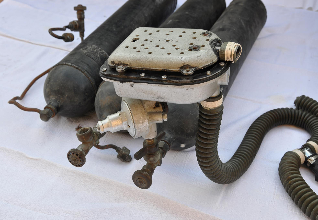
fig. 7 |
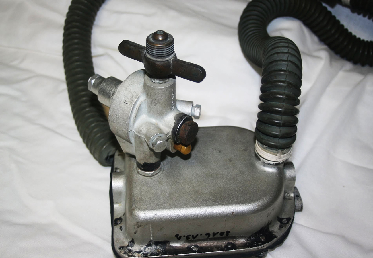
fig. 8 |
This equipment included three compressed air tanks of the welded ogives type, a first and second stage connected directly to each other and mounted on the valve of one of the three tanks, some copper piping, two partially damaged corrugated rubber hoses equipped with a metal "T" mouthpiece with a rubber nozzle, some pneumatic line fittings and the related valves. The regulator in particular (see Fig. 8) was made by a first stage derived from a pressure reducing valve used in compressed gas distribution systems (for example, in gas supply lines for oxyacetylene welding systems) and properly adapted for underwater applications (removal of the high and low pressure gauges, modification of the handle for adjusting the downstream pressure and application of a protective treatment to improve corrosion resistance) and by a rectangular shape second stage, probably made in cast aluminum. This latter component was directly derived from the device patented in France under the title “Perfectionnements aux detendeurs de gaz” (Improvements to gas regulators) by Emile Gagnan and his colleague Robert Bollard, both employees of Air Liquide, with an initial application dated November 21, 1940 and final publication on November 11, 1947 (patent number 927,821). The functioning scheme associated with the patent application (see Fig. 9) is shown in Fig. 10.
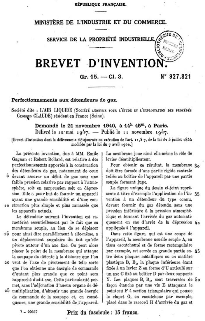
fig. 9 |
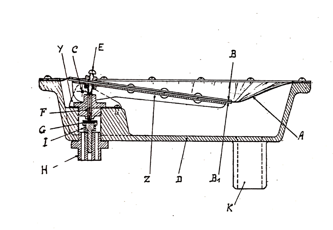
fig. 10 |
The same patent had also been requested in Switzerland on October 30, 1941 and subsequently filed on September 30, 1944 with number CH234418A. The device had been designed by the two Air Liquide engineers as an improvement to the gas feeding system for automotive engines, as an alternative to gasoline, which was practically unavailable in France at that time. To overcome the problem, Air Liquide therefore offered complete conversion kits on the market consisting of groups of tanks (often mounted on the roof of cars) and related distribution and engine gas feeding circuits (see Fig. 11). The same pressure reducing valve, with the simple addition of the air exhaust circuit with a duckbill valve and the relocation of the gas outlet connection, was later also included in the US patent application 2,485,039 filed on March 10, 1947, a patent subsequently granted on October 18, 1949 (see Fig. 12).
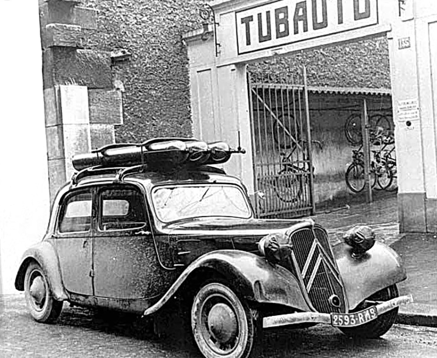
fig. 11 |
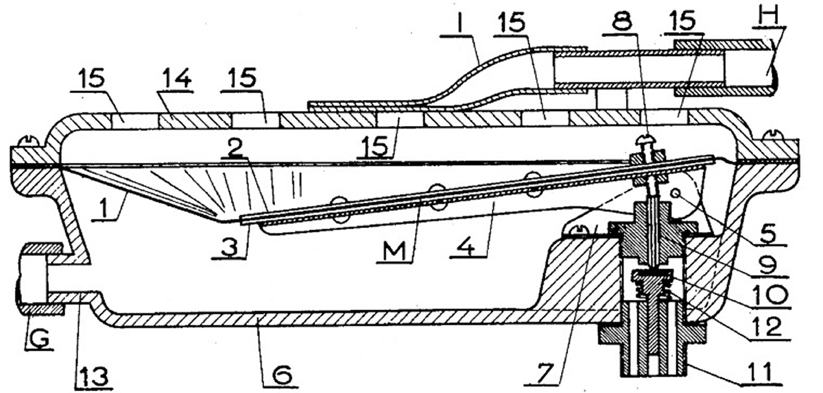
fig. 12 |
This device is also mentioned in the first chapter of Cousteau's famous book "The Silent World" published in 1953, where Cousteau describes his first conversation with Emile Gagnan in Paris in December 1942. After explaining to Gagnan what the device he had in mind was supposed to be able to do, the engineer retrieved the prototype of the device (which was initially made of Bakelite, a type of thermosetting epoxy resin) and showed it to Cousteau, saying, "Something like that?" Bakelite was typically used to make prototypes of these devices so that the units could be produced very quickly and the necessary validation tests could then be carried out without incurring in the greater costs and times required by standard manufacturing technologies. The fact that the museum prototype was made of aluminum indicates that this is likely the production version of the device.
On July 8, 1943, Air Liquide filed a new application (see Fig. 13) with the French Patent Office under the title “Perfectionnements aux installations pour la respiration des scaphandriers” (Improvements to breathing apparatus for divers). In this case, the patent application covered all the components necessary to build the breathing apparatus and specifically claimed the position of the exhaust valve in relation to that of the second-stage diaphragm (see Fig. 14). Patent number 937,032 was then granted and published on August 5, 1948. What struck me most when reading this patent documentation is that this time only Cousteau appears in the list of inventors, not Gagnan, whose contribution had been fundamental in achieving the final result!
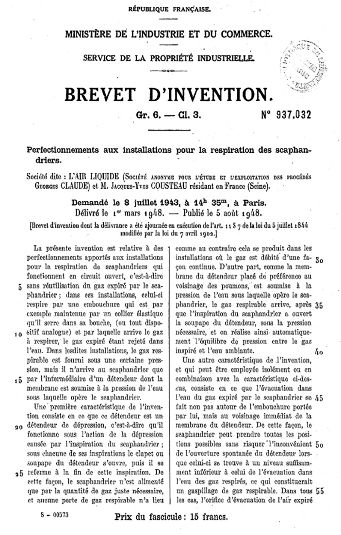
fig. 13 |
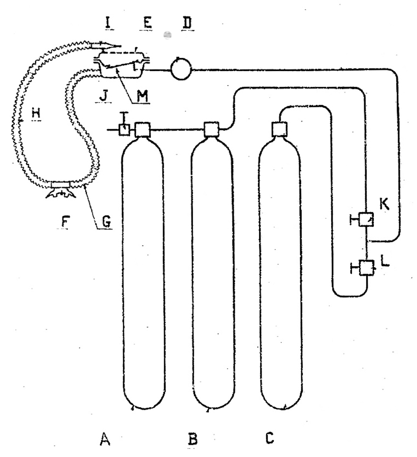
fig. 14 |
In 2017, some members of the Dumas Museum decided to attempt the reconstruction of a complete CG-43 SCUBA set, starting from the components contained in the wooden box mentioned above. Beyond the problem of recovering or rebuilding the missing components, the main challenge for the restoring personnel was to have references that clearly and in detail showed how this set was made. As far as was known, there were no drawings or other similar sets available, and the very few available pictures (see, for example, Fig. 15, which shows one of Cousteau's very first dives in the Marne River) were unable to provide all the necessary information. The only existing evidence showing this unit in operation was the documentary "Epaves" (Wrecks), produced by Cousteau in 1943 (see Fig. 16).
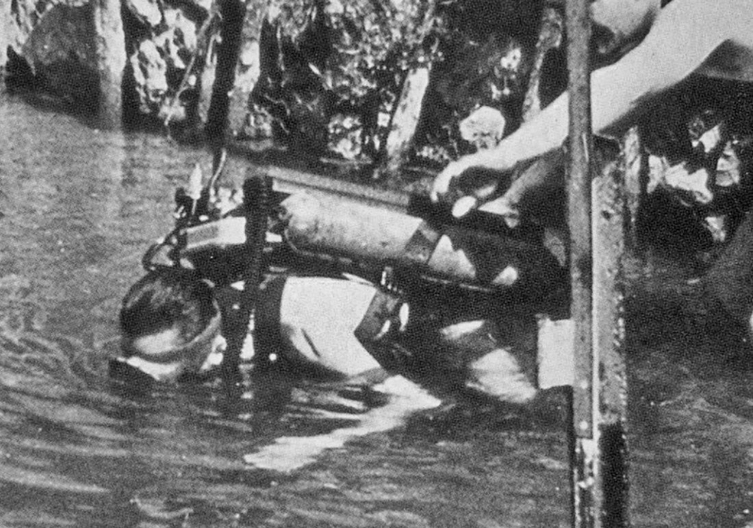
fig. 15 |
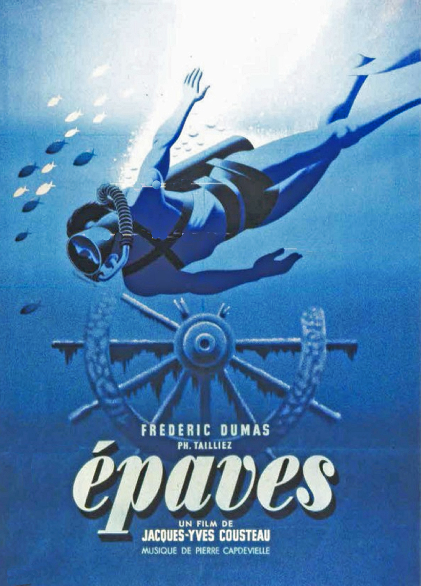
fig. 16 |
The documentary represents the first example of underwater cine footage showing a SCUBA unit in action. This was thoroughly analyzed by the restoring team, and all the information necessary to understand the setup of the unit's main components was captured from observing around fifty carefully selected frames (see Fig. 17 and Fig. 18).
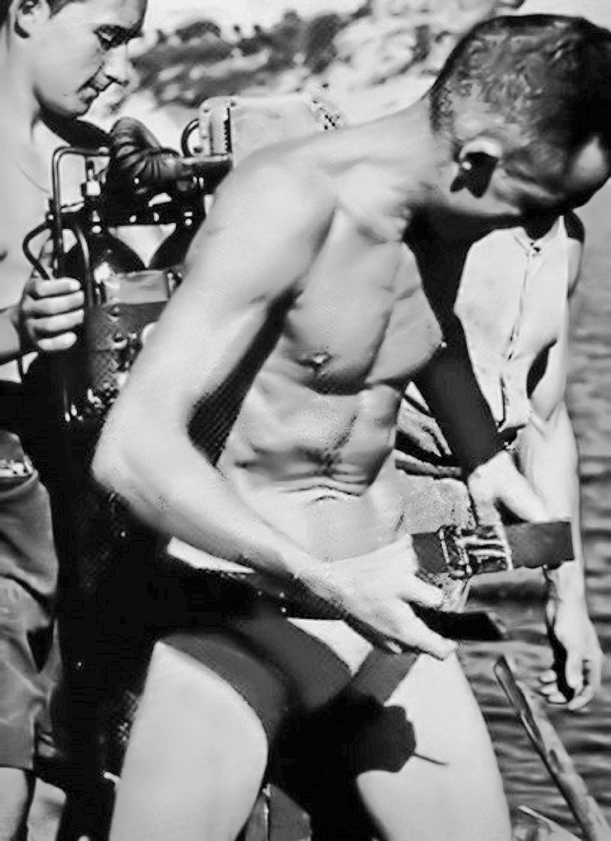
fig. 17 |
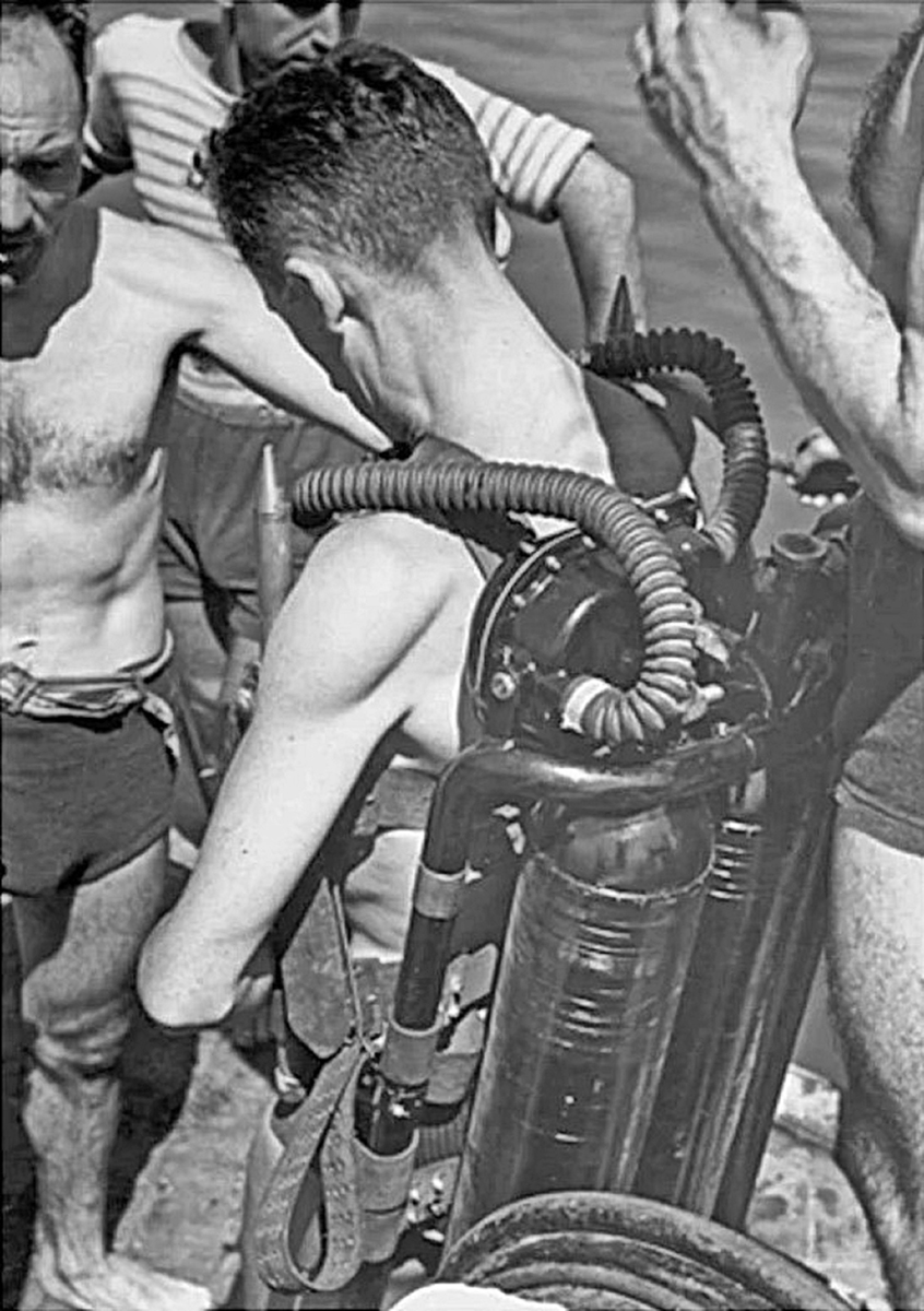
fig.18 |
In most of the video shots, the full three-tank SCUBA set is worn by Dumas, who is also the protagonist of the main underwater scenes. There is only one very brief sequence in which Cousteau is seen diving but, strangely, with the "hookah" version of the breathing set, that is, with an air hose fed from the surface (see Fig. 19). Some time ago, I found some photos online of this version of the Cousteau-Gagnan having a Bakelite body (see Fig. 20).
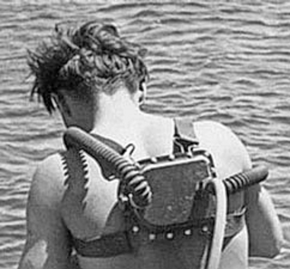
fig. 19 |
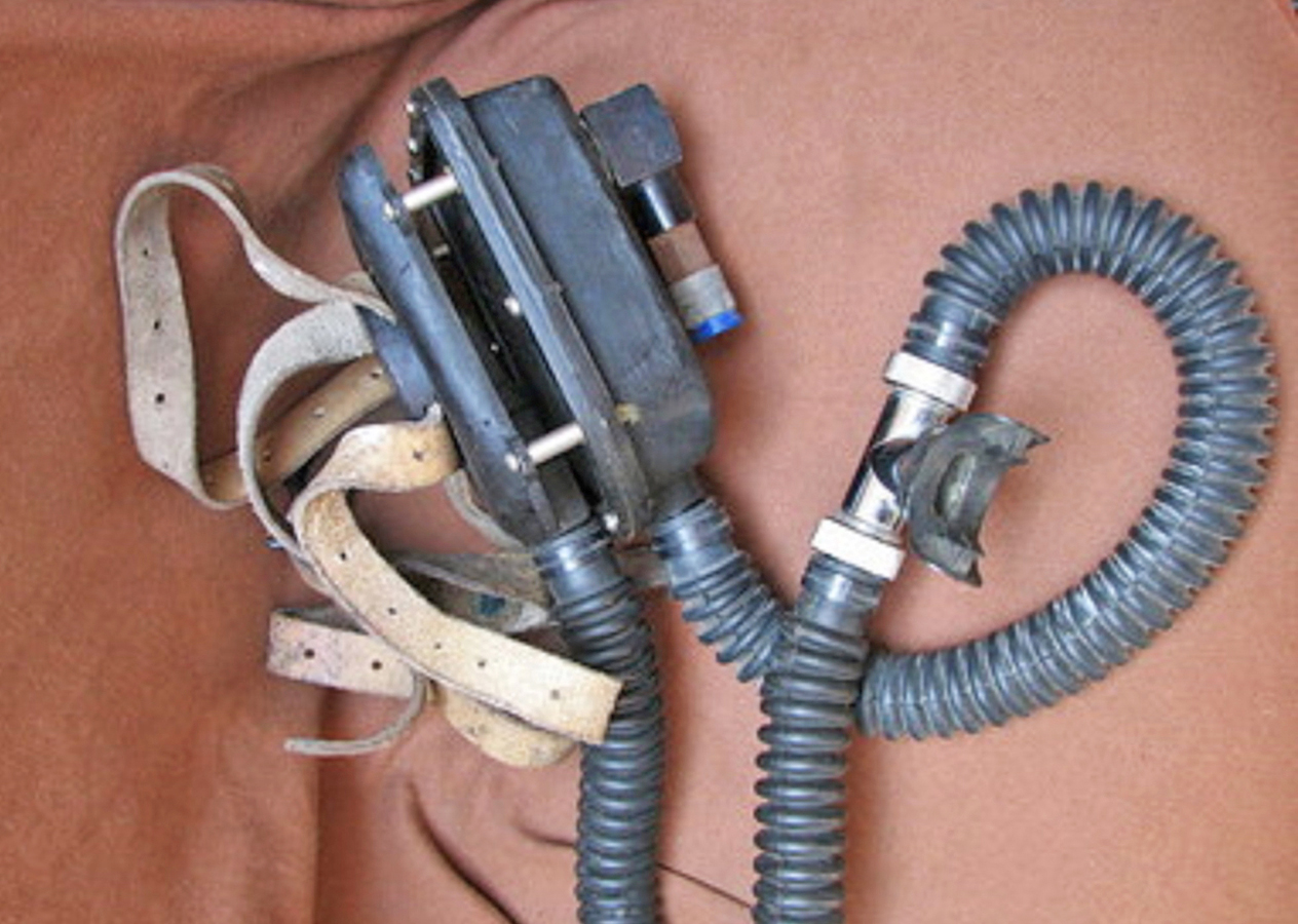
fig. 20 |
The rebuilding of this breathing set was completed in 2020 and then documented in a specific article published in the French magazine "Subaqua" the magazine of the French Federation of Underwater Activities, in issue no. 291 of July-August 2020. The effort required for the rebuilding was certainly huge, but the result achieved is also highly significant as a historical testimony to the development of these devices. The complete rebuilt SCUBA set is now visible in one of the rooms of the Dumas Museum (see Fig. 21, Fig. 22, Fig. 23 and Fig. 24).
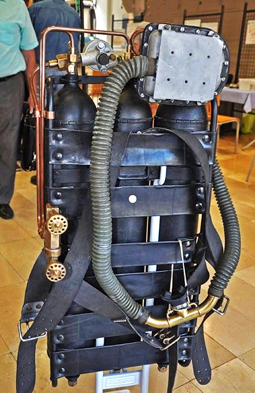
fig. 21 |
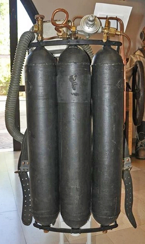
fig. 22 |
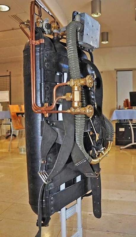
fig. 23 |
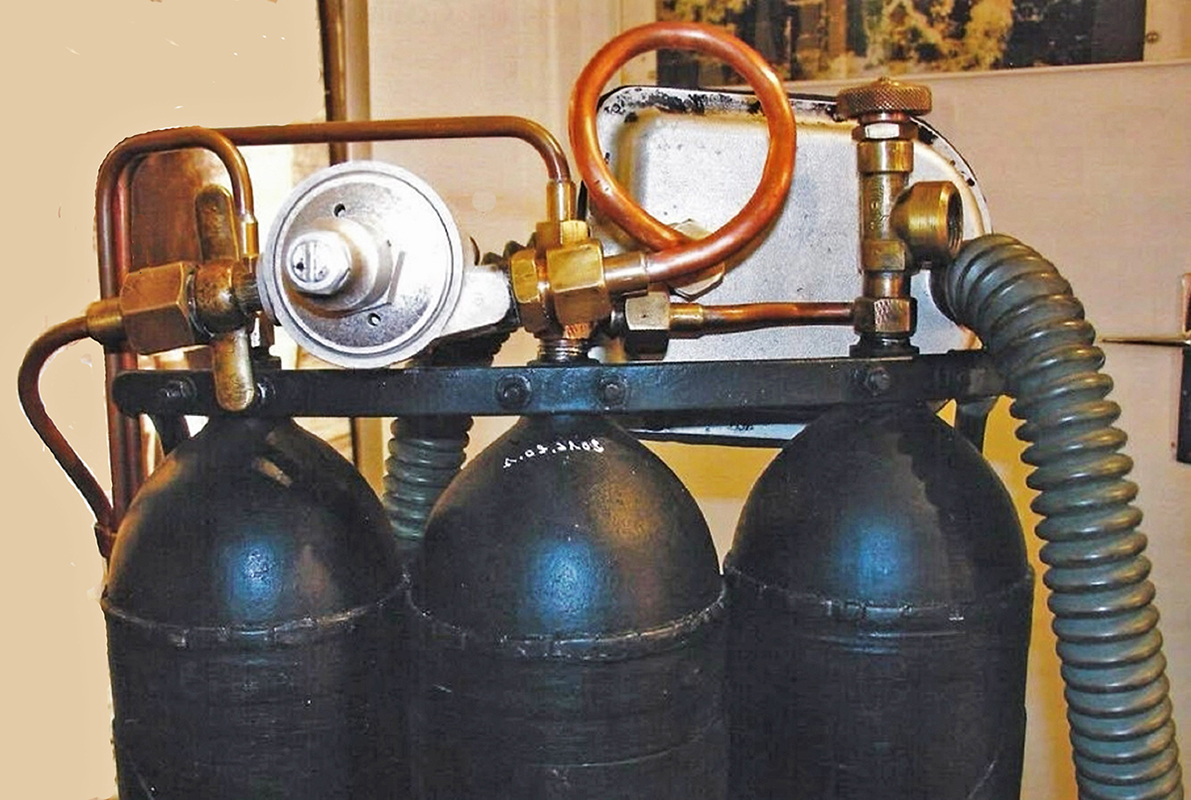
fig. 24 |
Observing the breathing apparatus at the end of the reconstruction and restoration work and considering the initial condition of the material found inside the box, we can deduce the main activities undertaken by the museum team during the project:
- Construction of a welded frame made by steel tubes and profiles to support and connect the three tanks and all other components of the SCUBA set.
- Rebuilding of all copper pipes and fittings.
- Complete reconstruction of the pneumatic circuit following as closely as possible the configuration taken from the documentary "Epaves". The two pressure reducing valves were separated and then connected to the circuit according to the final layout. The fittings and valves contained in the box were reused. The missing ones were found elsewhere or completely rebuilt. This setup is identical to that shown in both French patent number 937,032 and U.S. patent number 2,485,039 cited above.
- Complete reconstruction of the connecting straps installed between the frame tubes (which also provide a support surface for the diver's back) and the harness. All these components were made from leather strips.
- Reconstruction of the typical "handlebar" mouthpiece connected to the corrugated hoses, a feature also found in the early production series of the CG-45 (Fernez type).
- Replacement of damaged corrugated hoses.
Before the rebuilt of the Sanary-sur-Mer SCUBA set, another French collector had the opportunity to closely analyze and measure the aluminum second stage. From these measurements, he then created a three-dimensional model of the second stage body. Finally, starting from this model, he produced several copies of this component made with a 3D printer and using gray plastic material. The sample in the display case was made from one of these plastic bodies.
Although the final looking of the regulator is nice (after smoothing the surfaces with sandpaper, then painting the plastic body and finally adding the corrugated hoses and the mouthpiece), this work was incomplete because the second stage was basically an empty shell without internal components, and the first stage was missing.
Hence the idea of building a display model of the CG-43 regulator for my collection, in the same configuration as the original prototype contained in the box donated to the museum and later reassembled in the version seen in the documentary "Epaves". This unit would have to be complete with the first stage and all the internal components of the second stage. Off course, without the original tanks and valves, the possibility of building an entire breathing set like the one in the Dumas Museum was out of my possibilities.
The first step was to obtain a replica of the second-stage body from the collector who had them made by 3D printer. The two body halves and the kit included in the package offered for sale by the French collector are shown in Figs. 25, 26, 27, and 28.
Observing the breathing apparatus at the end of the reconstruction and restoration work and considering the initial condition of the material found inside the box, we can deduce the main activities undertaken by the museum team during the project:
- Construction of a welded frame made by steel tubes and profiles to support and connect the three tanks and all other components of the SCUBA set.
- Rebuilding of all copper pipes and fittings.
- Complete reconstruction of the pneumatic circuit following as closely as possible the configuration taken from the documentary "Epaves". The two pressure reducing valves were separated and then connected to the circuit according to the final layout. The fittings and valves contained in the box were reused. The missing ones were found elsewhere or completely rebuilt. This setup is identical to that shown in both French patent number 937,032 and U.S. patent number 2,485,039 cited above.
- Complete reconstruction of the connecting straps installed between the frame tubes (which also provide a support surface for the diver's back) and the harness. All these components were made from leather strips.
- Reconstruction of the typical "handlebar" mouthpiece connected to the corrugated hoses, a feature also found in the early production series of the CG-45 (Fernez type).
- Replacement of damaged corrugated hoses.
Before the rebuilt of the Sanary-sur-Mer SCUBA set, another French collector had the opportunity to closely analyze and measure the aluminum second stage. From these measurements, he then created a three-dimensional model of the second stage body. Finally, starting from this model, he produced several copies of this component made with a 3D printer and using gray plastic material. The sample in the display case was made from one of these plastic bodies.
Although the final looking of the regulator is nice (after smoothing the surfaces with sandpaper, then painting the plastic body and finally adding the corrugated hoses and the mouthpiece), this work was incomplete because the second stage was basically an empty shell without internal components, and the first stage was missing.
Hence the idea of building a display model of the CG-43 regulator for my collection, in the same configuration as the original prototype contained in the box donated to the museum and later reassembled in the version seen in the documentary "Epaves". This unit would have to be complete with the first stage and all the internal components of the second stage. Off course, without the original tanks and valves, the possibility of building an entire breathing set like the one in the Dumas Museum was out of my possibilities.
The first step was to obtain a replica of the second-stage body from the collector who had them made by 3D printer. The two body halves and the kit included in the package offered for sale by the French collector are shown in Figs. 25, 26, 27, and 28.
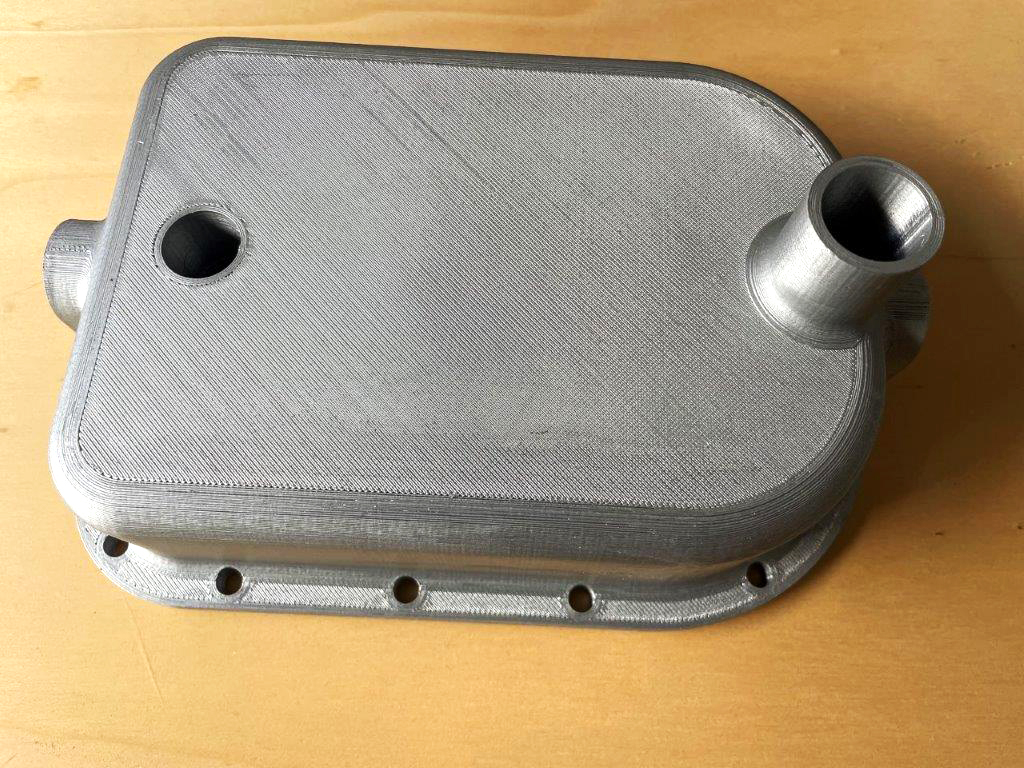
fig. 25 |
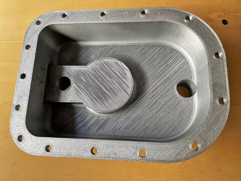
fig. 26 |
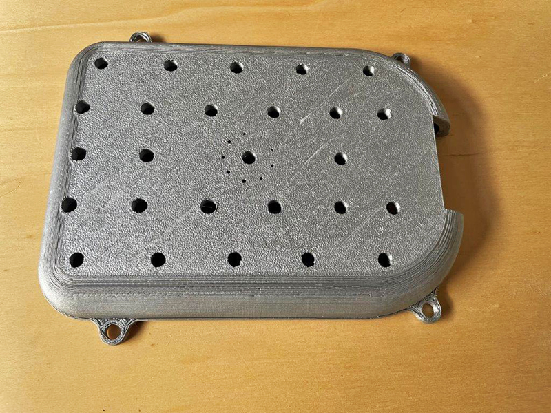
fig. 27 |
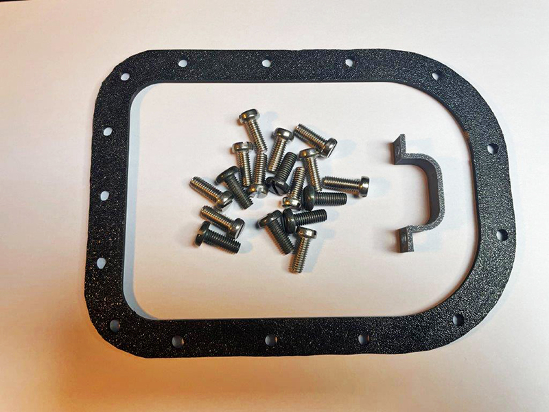
fig. 28 |
Now it was a matter of understanding how to build the internal components of the second stage. The main source of information for this purpose was the cross-section of this device shown in Figs. 10 and 12, taken from various patent applications. While these schemes were exhaustive regarding the kinematics in the longitudinal plane of the device, they lacked information on the lateral plane and pictures showing the complete internal mechanism. Here too, the French collector specialized in the La Spirotechnique products offered his support by providing the pictures shown in Figs. 29, 30, 31, and 32.
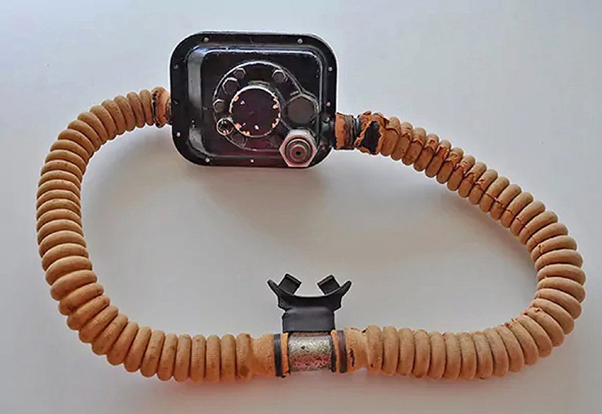
fig. 29 |
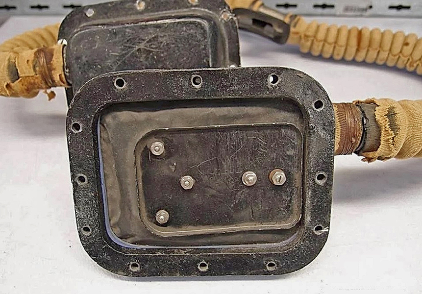
fig. 30 |
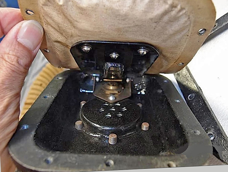
fig. 31 |
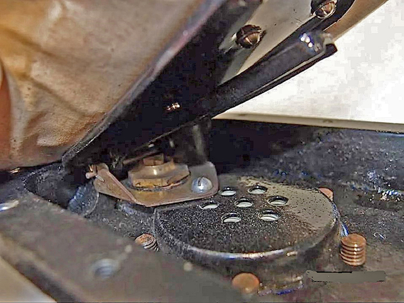
fig. 32 |
These pictures show the prototype of the CG-45, with a Bakelite body, preserved in the Aqualung company collection of historical equipment. This unit represents the evolution of the Cousteau-Gagnan regulator in the phase immediately preceding the start of production of this device, which was launched on the market in 1946 by the newly founded La Spirotechnique, a company created by Air Liquide to produce and market this equipment.
As can be seen in the previous pictures, in this prototype, the first stage had been redesigned and integrated into the regulator body, while the second stage remained the same as the original 1940 design. The final construction scheme of the regulator would then be frozen for the start of production, as shown in Figs. 33 and 34. Note that, in the final version, the second-stage valve had been completely redesigned according to the "downstream" operating principle. Unlike the previous "upstream" solution, this did not require the use of a safety valve to prevent the risk of breaking in the low-pressure line in the event of an air leak in the first stage. These safety valves were normally installed on the first pressure-reducing stages, such as the one preserved in the Sanary-sur-Mer Museum.
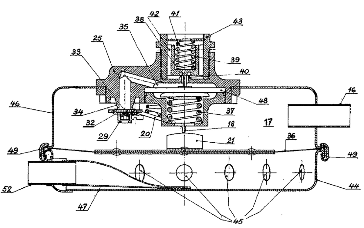
fig. 33 |
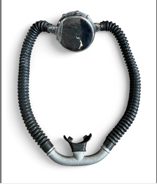
fig. 34 |
Using the above information and having access to the geometric dimensions of the second stage body sample, it was possible to redesign the device, complete with all the various internal components, the corrugated hoses, and the mouthpiece. The results of this work are shown in Figs. 35, 36, 37, 38, 39, 40, 41, and 42.
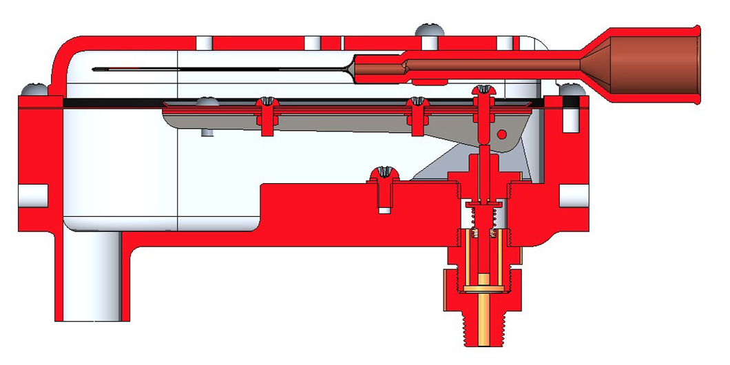
fig. 35 |
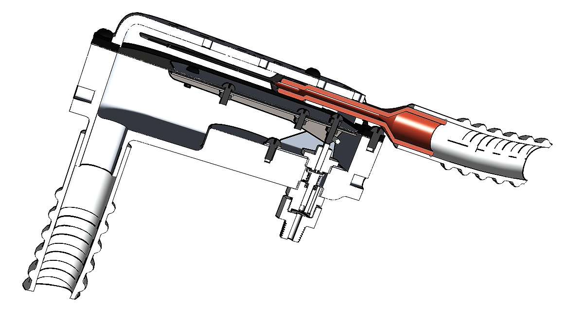
fig. 36 |
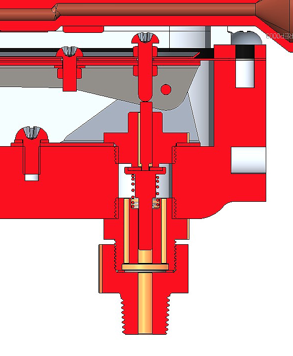
fig.37 |
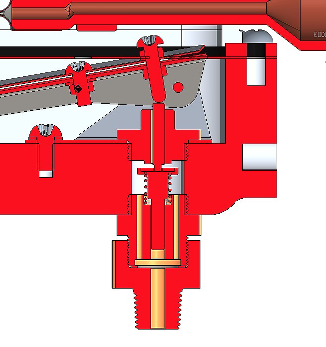
fig. 38 |
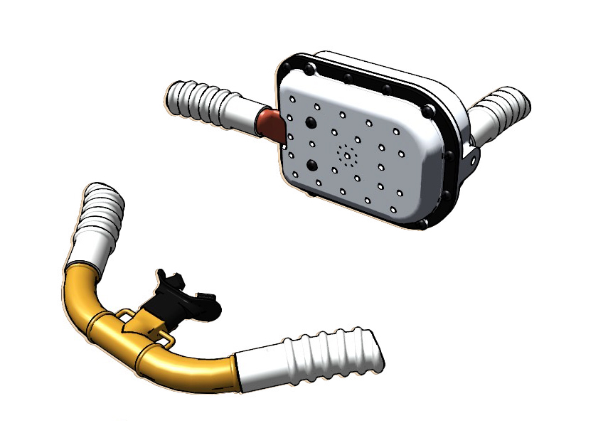
fig. 39 |
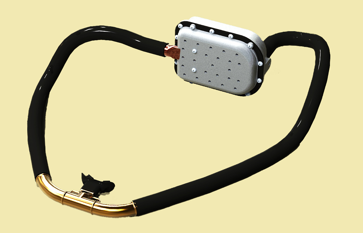
fig. 40 |
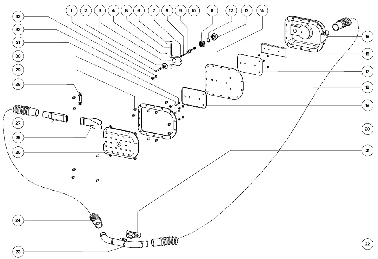
fig. 41 |
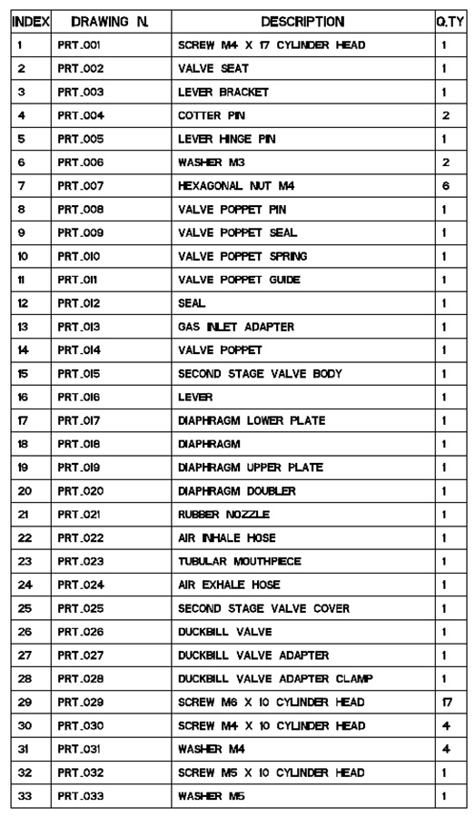
fig. 42 |
While generating the virtual model of the CG-43 second stage, it was realized that, during the rebuilt of the Dumas Museum's SCUBA set, the position of the exhaust hose had been moved on the opposite side of the second stage with respect to that of the regulator contained in the box donated by Robert Buffaz's family. This configuration was the one used by the French collector in the 3D remake of the regulator body, the model from which the plastic components purchased for this project were then produced. To rebuild something as similar as possible to the breathing apparatus used in the documentary "Epaves", the position of the exhaust hose on the second stage body would also have to be reversed in this work. The 3D model of the regulator's second stage was therefore modified by moving the exhaust hose outlet to the opposite side of the cover and modifying the connection between the exhaust hose and the duckbill valve, including its fastening clamp. These modified pieces were then manufactured in plastic material with a 3D printer (see Figs. 43 and 44).
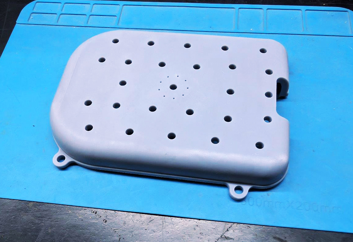
fig. 43 |
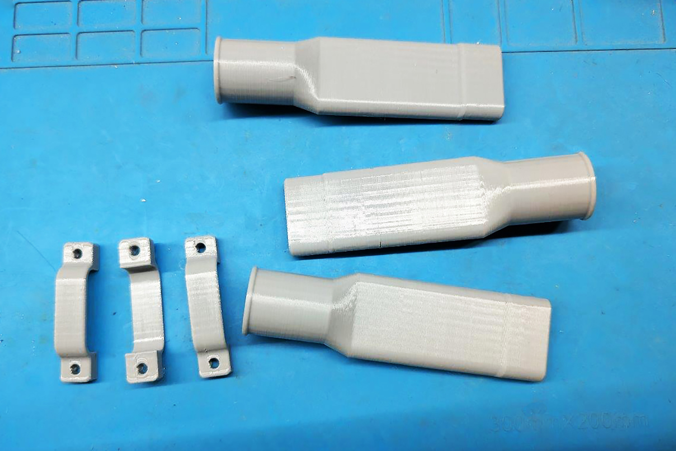
fig. 44 |
Starting from these drawings, the internal components of the second-stage mechanism were built at a specialized mechanical workshop, using brass (for the machined components) and stainless steel sheet (for the parts made by cutting and bending) as the basic materials. At the end of the mechanical manufacturing phase, the obtained components are shown in Figs. 45, 46, 47, and 48.
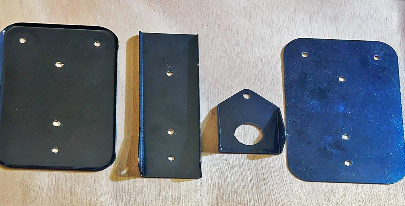
fig. 45 |
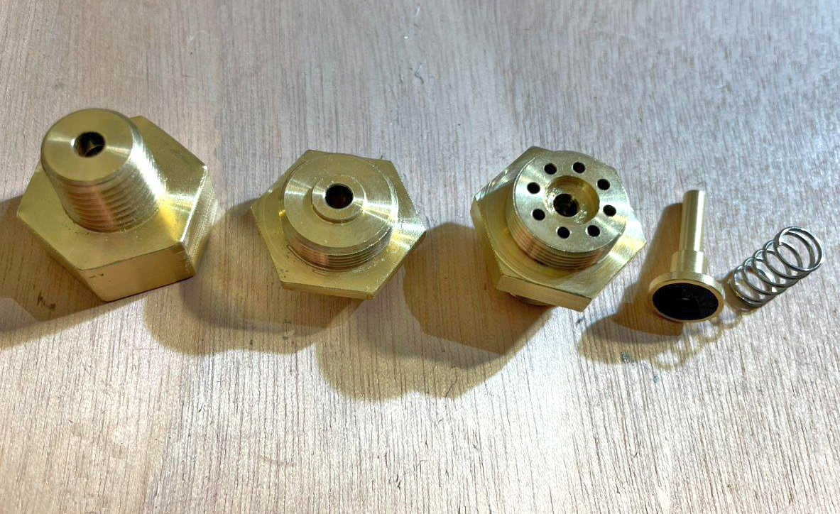
fig. 46 |
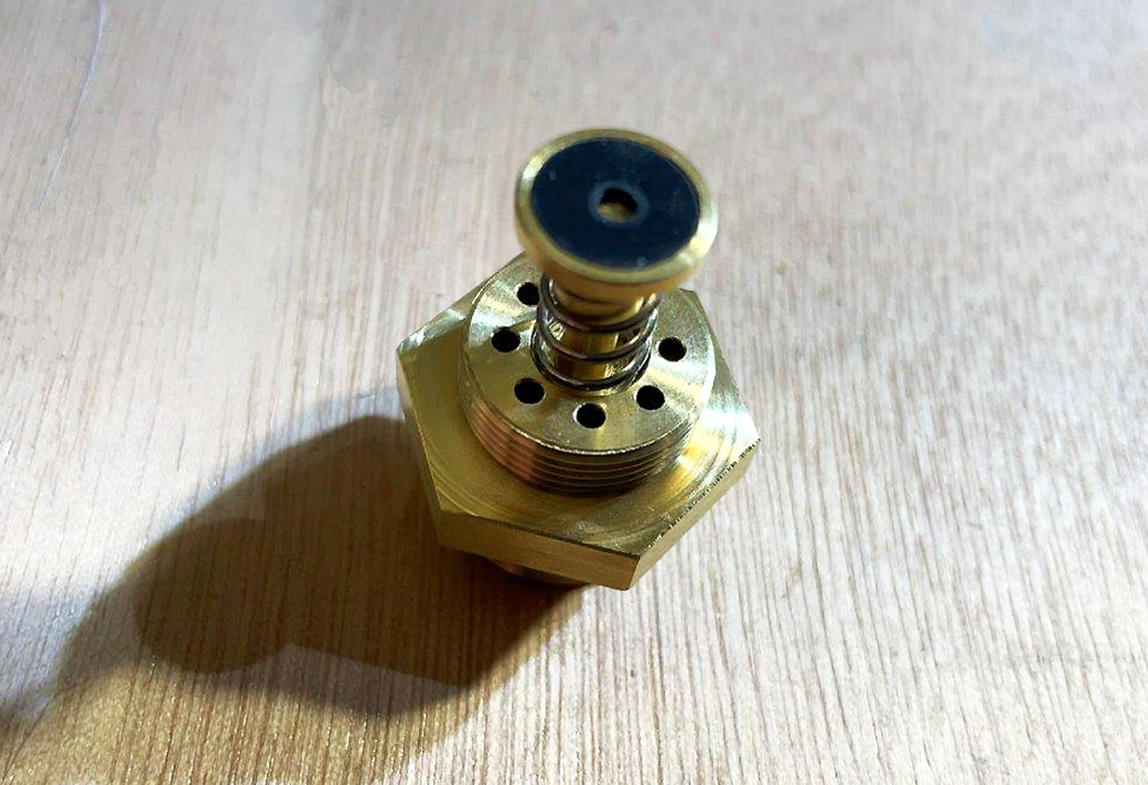
fig. 47 |
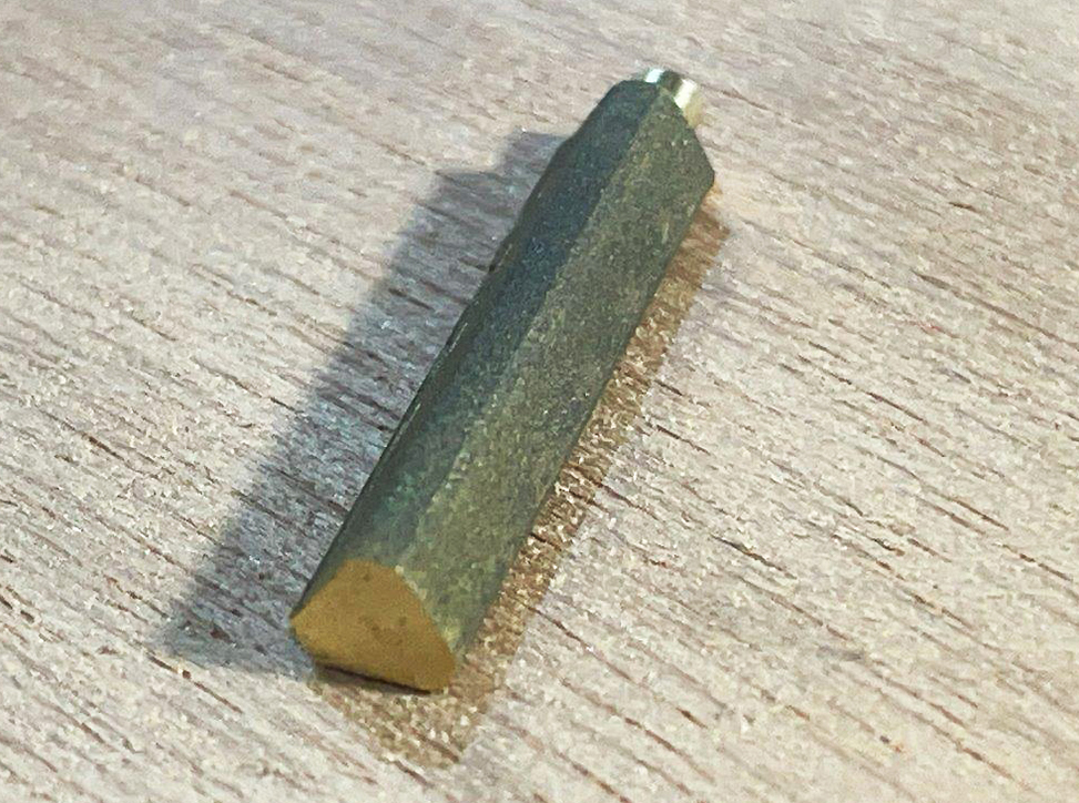
fig. 48 |
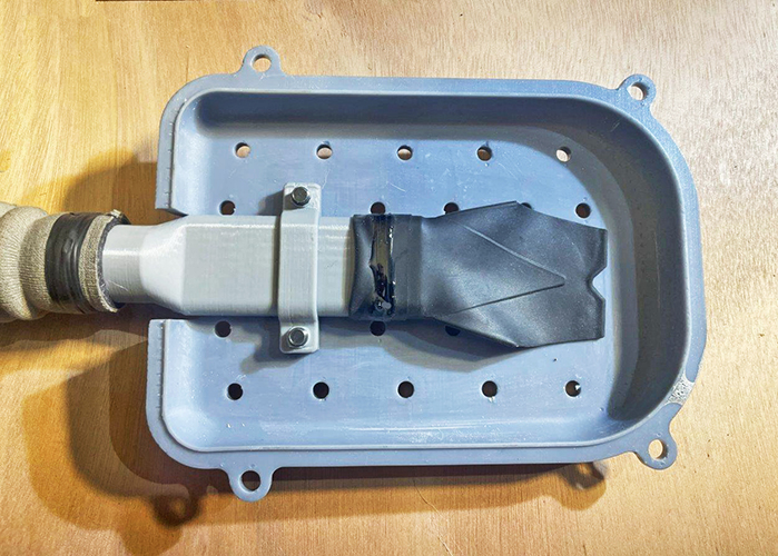
The diaphragm was made from a 0.5 mm thick silicone rubber sheet having the necessary elasticity and strength. At this point, the second stage, after sanding and painting the plastic body, was completed and reassembled as shown in Figs. 49, 50, 51, 52, 53, 54, 55, and 56.
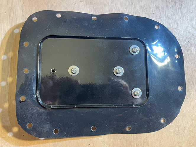
fig. 49 |
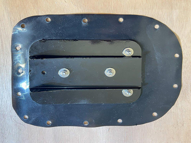
fig. 50 |
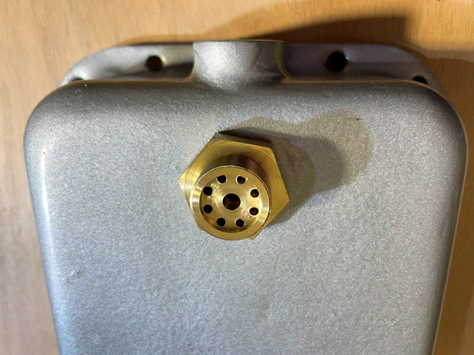
fig. 51 |
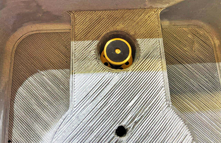
fig. 52 |
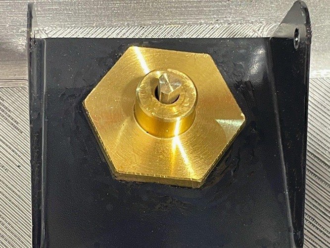
fig. 53 |
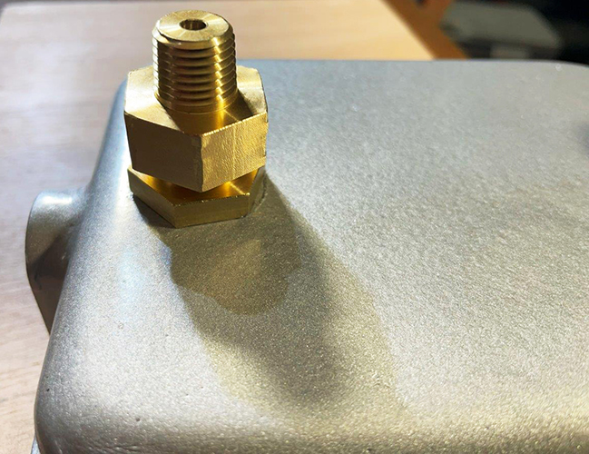
fig. 54 |
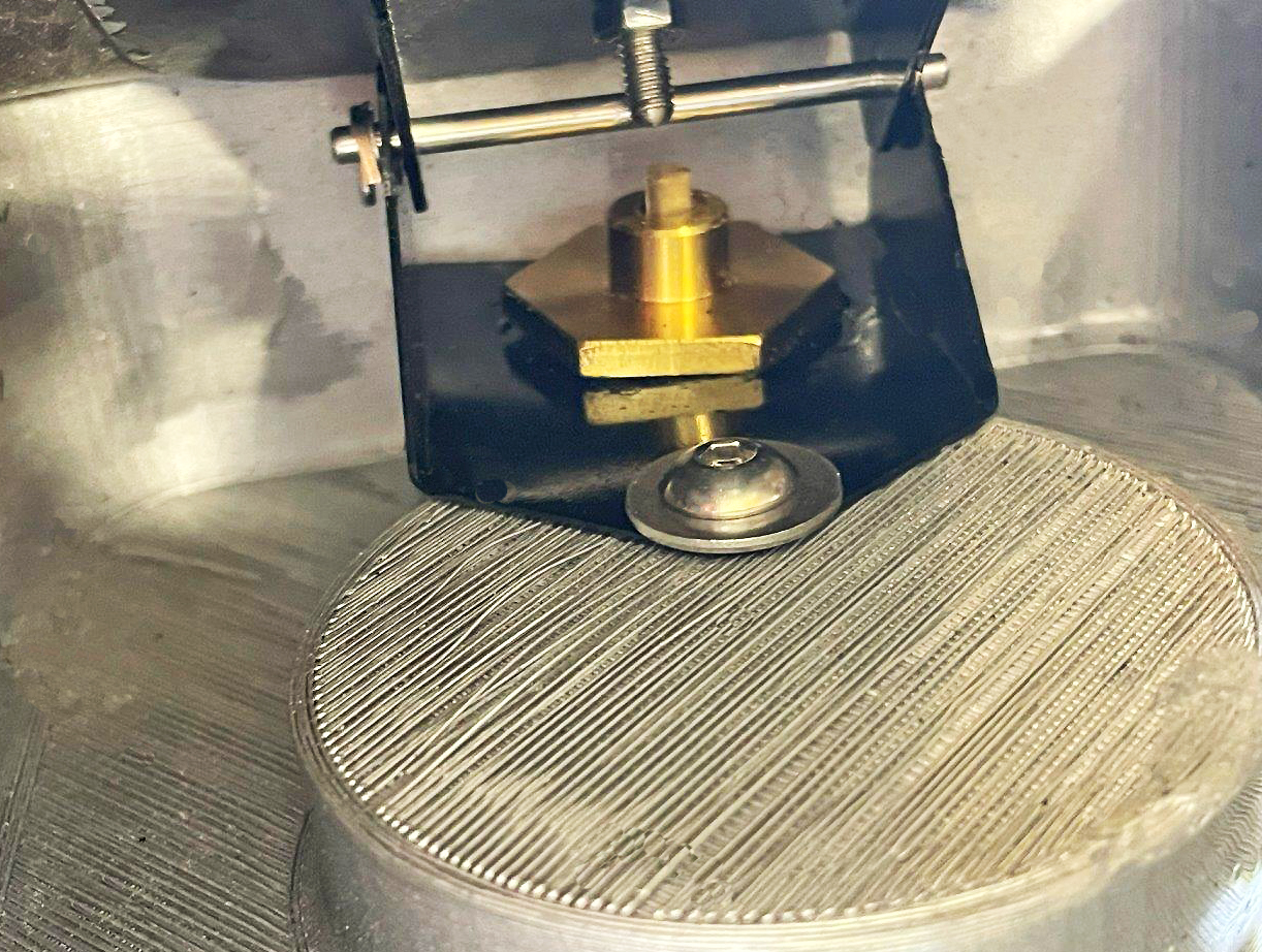
fig.55 |
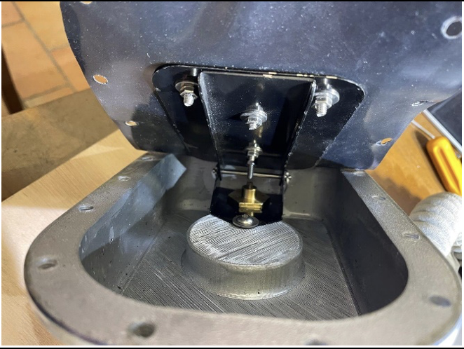
fig. 56 |
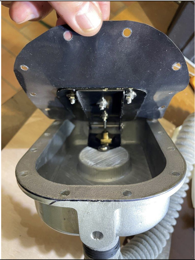
fig. 57 |
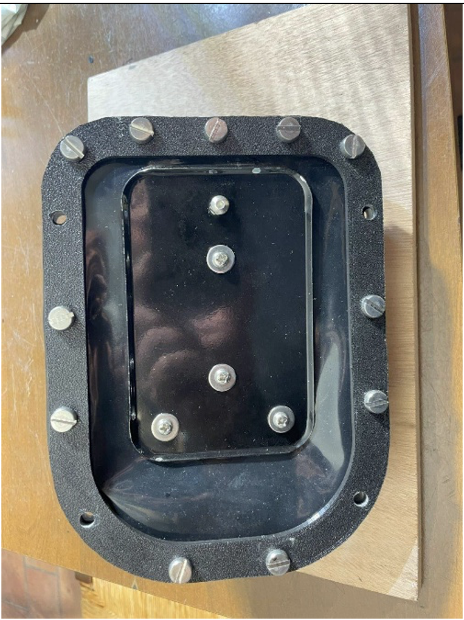
fig. 58 |
About the first stage, having no hope of finding somewhere the same type of pressure reducing valve as the original model, it was decided to look for something as similar as possible, possibly from the same historical period. After extensive online research, an old gas pressure reducing was found in the USA and then purchased (see Fig. 59 and Fig. 60).
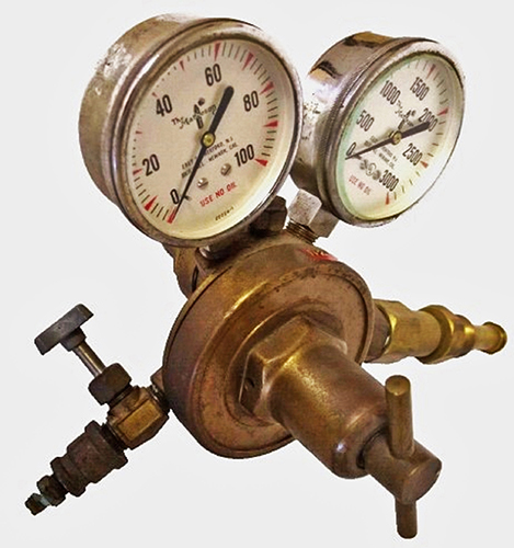
fig. 59 |
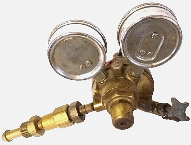
fig. 60 |
Although the location of the various connections was not the same as the original sample, it was decided that the unit was acceptable for the project's purpose. Therefore, this pressure reducing valve was submitted to the following modifications:
- Removal of both high and low pressure gauges and installation of plugs on the corresponding connection ports.
- Removal of the pressure reducing valve installed on the high-pressure line (then replaced by a threaded cover).
- Repositioning of the high-pressure line connection fitting and modifying its threaded connection
- Modification of the low-pressure line connection fitting to make it compatible with coupling to the second-stage body.
- Modification of the downstream pressure adjustment screw and addition of a locking nut.
- Painting of the pressure reducing valve body in silver color, similar to that observed in the museum breathing set.
Figures 59 and 60 show the first stage pressure reducing valve after the above modifications.
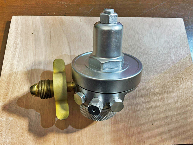
fig. 61 |
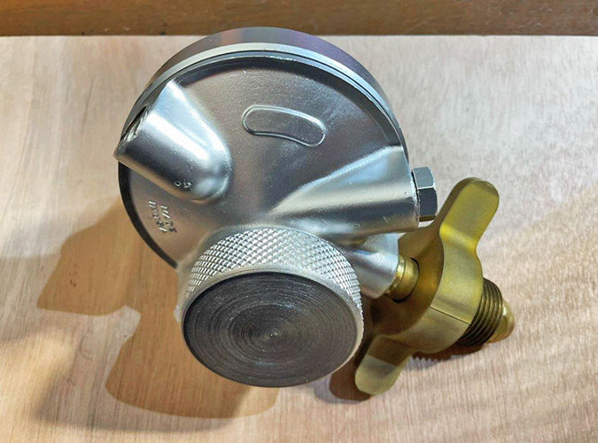
fig. 62 |
Another element to be made was the typical metal "handlebar" mouthpiece, similar to the museum's unit after the rebuilt which is clearly visible also in Cousteau's documentary. In fact, the mouthpiece with its nozzle originally contained in the box donated to the museum, looks to be the type used on the Mistral regulator model (it was likely added at a later stage). Again, considering the complexity and the consequent high cost of the original production process (cutting and bending brass tubes, then welding together the pieces, and finally chrome plating the assembly), it was decided to make this component using 3D printing (see Fig. 63). The handlebar mouthpiece, after smoothing its external surface, was treated with a special gold-effect paint to obtain a final looking similar to that of the museum component. The final component so obtained is shown in Fig. 64.
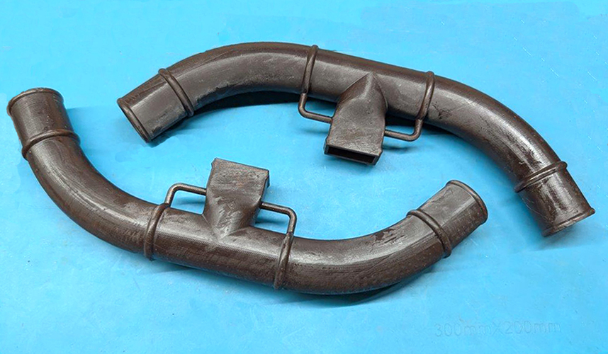
fig. 63 |
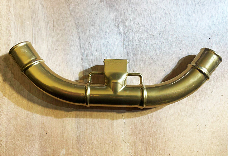
fig. 64 |
The corrugated rubber hoses with one-inch size ends were purchased on eBay, while other components were already available, such as the duckbill valve, to be installed on the exhaust outlet, and the original rubber nozzle, to be mounted on the central outlet of the handlebar mouthpiece.
The final assembly of the regulator was then carried out as described below.
To secure the corrugated hoses to the mouthpiece and to the second-stage body, a solution widely used on these devices at that time was chosen, since the typical hose clamps, components that would appear on the market a few years later, were not yet available. These solutions consist of copper wire or textile wire (in the latter case sealed with epoxy resin) that are then protected with rubber tape (see Figs. 65, 66, 67 and 68).
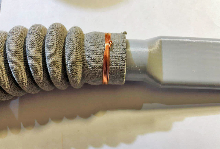
fig. 65 |
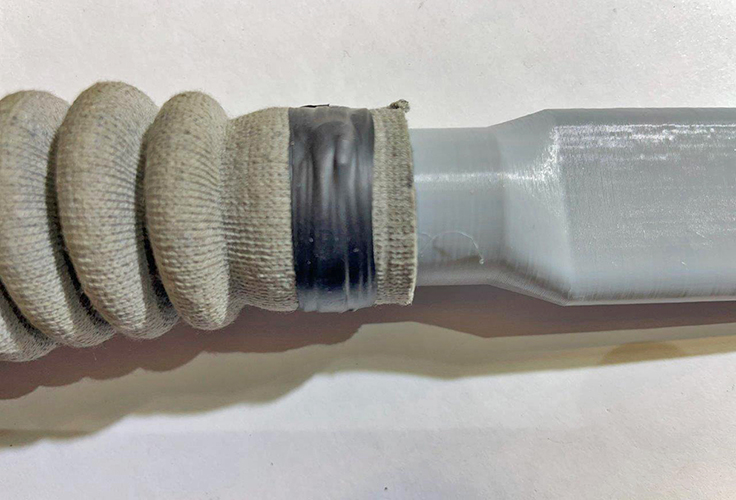
fig. 66 |
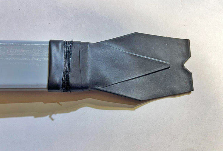
fig. 67 |
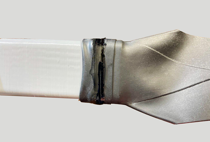
fig. 68 |
The final result of the work is highlighted in Figs. 69, 70, 71, 72, 73, 74, 75 and 76, which show the regulator after the building phase and finally placed in its final location inside one of the display cases of my small museum in Gubbio. In the display case, the CG-43 was placed alongside one of the samples of what would later become its successor: the Cousteau-Gagnan model CG-45 regulator. This particular unit, serial number 2042, belonged to François Dorado, a member of the Cousteau Team, who often sailed on the Calypso.

fig. 69 |
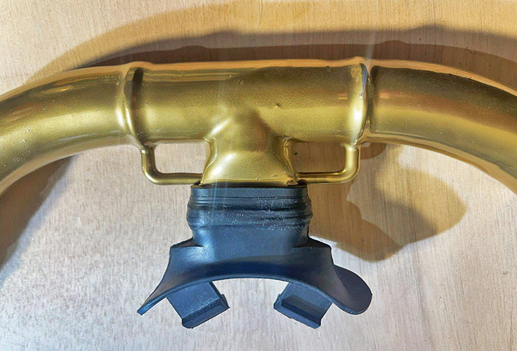
fig. 70 |
fog. 71 |
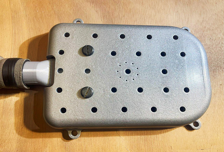
fig. 72 |
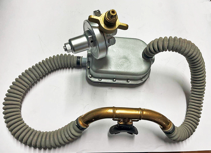
fig. 73 |
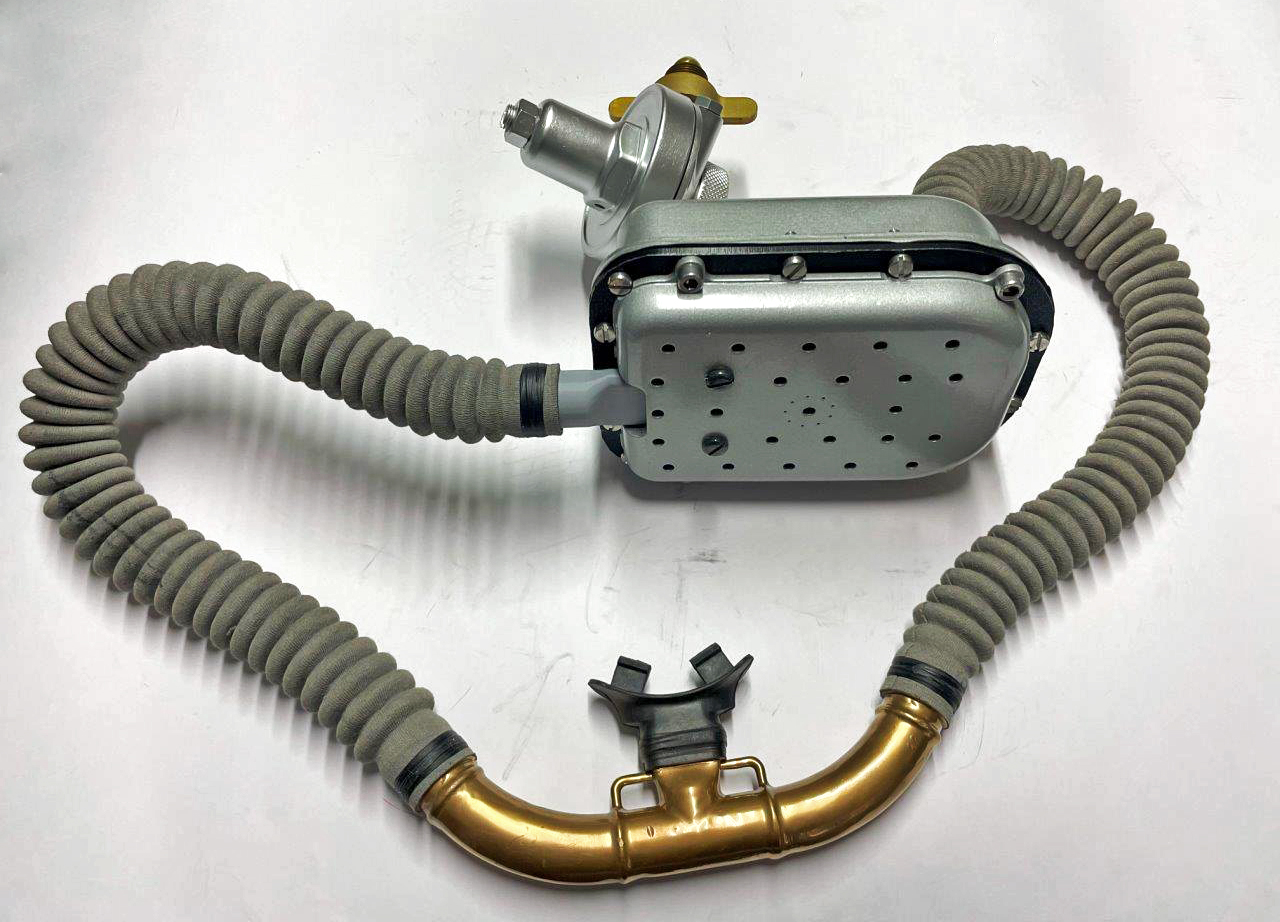
fig. 74 |
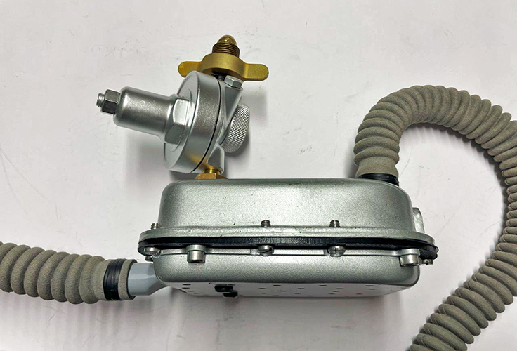
fig. 75 |
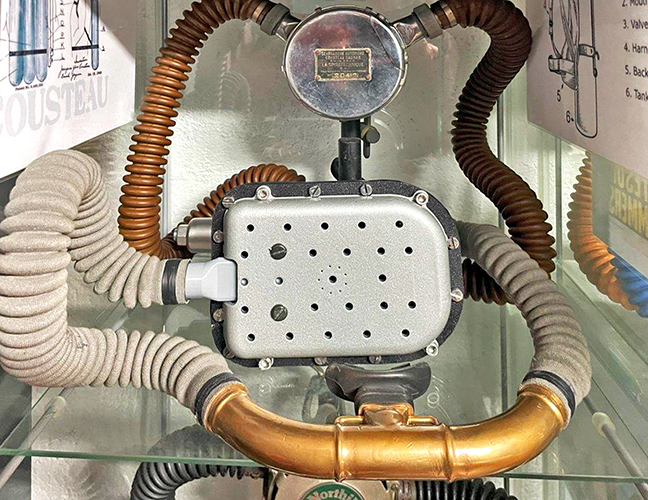
fig. 76 |
Finally, another building project of one of these iconic pieces of equipment in the history of sports and recreational diving came to its conclusion. It is hoped that this article could contribute to the dissemination of knowledge about those fascinating and adventurous years, the dawn of modern diving era, years that all enthusiasts would have loved to experience firsthand, just like Cousteau and his group of "Mousquemers".
______________