Maurizio Baldinucci
Few months after completing my latest project, the rebuilding of a replica of the prototype Cousteau-Gagnan CG-43 regulator, a work described in a dedicated article published in the "Equipment Restoration" section of Luigi Fabbri's website www.blutimescubahistory.com and in issue 24-12/2025 of the magazine TauchHistorie published by HDS Germany, I was contacted by Luc Fuster, the French collector who had provided me with essential data and information to complete this work. To get started, Luc, for whom I had recently produced the components to complete his replica of this regulator, told me that the name CG-43, often used to indicate this first prototype, is actually a term coined by historians and collectors but never existed in the minds of the two inventors, Jacques Y. Cousteau and Émile Gagnan. The correct name should instead be "Air Liquide Cousteau system regulator". But the real reason Luc was contacting me was the following: "Would it have been possible, in my opinion, to also make a replica of the later CG-45 prototype from which the few photos available online were taken and used to clarify some construction details of the CG-43?" For those who haven't read the previously cited article, I remind you that this prototype (see Fig. 1 and Fig. 2) is owned by Aqualung, a well-known sports diving equipment manufacturer that recently became part of the multinational group Head, and is often shown to the public at trade shows or other important events.
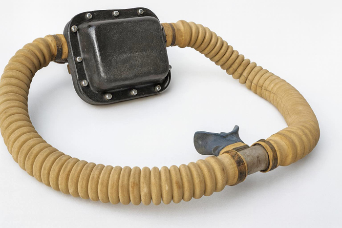
fig. 1 |
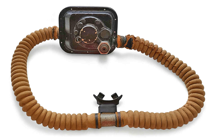
fig. 2 |
Given its unique nature and its historical value as a direct testimony of the embryonic stage of recreational self-contained diving, the company is extremely protective of this unit, the possession of which, for collectors, remains an unattainable dream. Having even a non-functioning replica of this unit in their collection is, however, a significant goal for many of them. This unit, which represents the link between the original scuba set built by Gagnan, through assembling components originally designed for other applications, and the production CG-45 device, was discovered in the late 1980s by pure chance by Frédéric Jacomet (see Fig. 3), a key figure in the history of La Spirotechnique before and Aqualung later. Jacomet had recently served as Global Technical & Training Center Director - Aqualung Corporate for Aqualung before his passing a few months ago.
The regulator, forgotten for decades, was contained inside a cardboard box found in the warehouse of La Spirotechnique's new headquarters in Carros, Provence, southern France. The box was among other materials that had been moved to the new factory in 1976 during the relocation from the original headquarters in Crépy-en-Valois. The famous photograph of Commander Cousteau holding this extraordinary regulator dates back to 1993, at the Paris Boat Show (see Fig. 4). On that occasion, the La Spirotechnique team proudly presented him with this exceptional discovery, emerging from a simple, dusty cardboard box: a tangible fragment of a technical and human adventure that marked the history of autonomous diving.
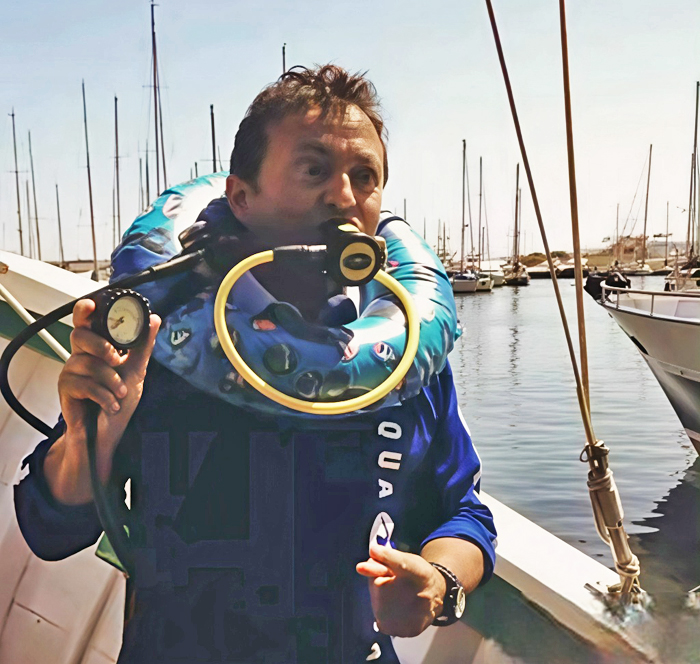
fig. 3 |
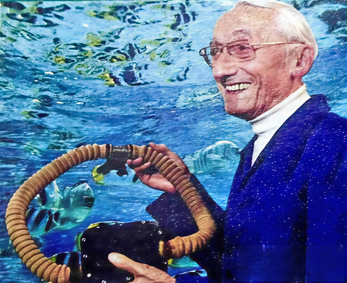
fig. 4 |
Luc had long searched for data and information on this unit but, beyond the few photos posted online by Aqualung itself and those from trade shows where the regulator was exhibited to the public (see Luc Fuster's photo in Fig. 5 next to the prototype), he had been unable to find any other useful information. For my part, I had been very clear with Luc: "If no other important and verified information about this unit came to light, I did not believe it was possible to begin any project to rebuild a replica". The real turning point that allowed this work to begin came a few months ago when Manuel Cabrère, the current Group Product Training and e-Learning Coordinator at Aqualung (see Fig. 6), agreed to provide Luc with more photos of this unit and, more importantly, the measurements of its main geometric elements. Cabrère took several photos of the device from various angles and measured some of its main elements following the instructions we had provided him.
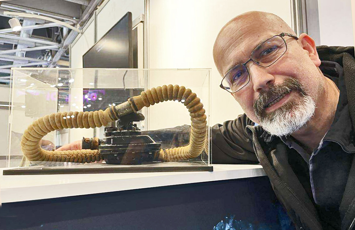
fig. 5 |
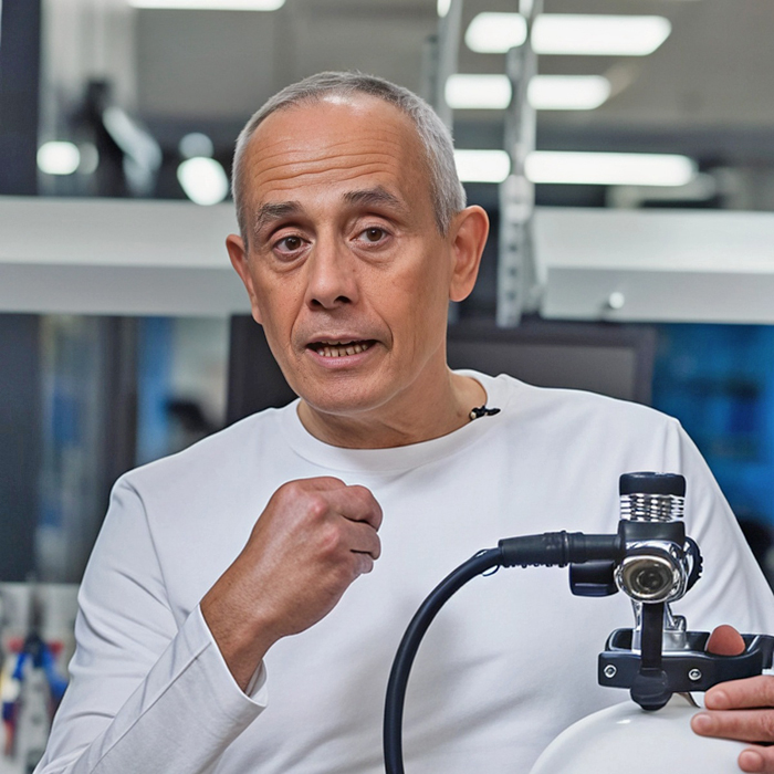
fig. 6 |
A selection of these photos, from which it was also possible to obtain the main dimensional information of the device, thanks to the use of a caliper and a ruler, is shown in the following Figs. 7, 8, 9, 10, 11, 12, 13 and 14.
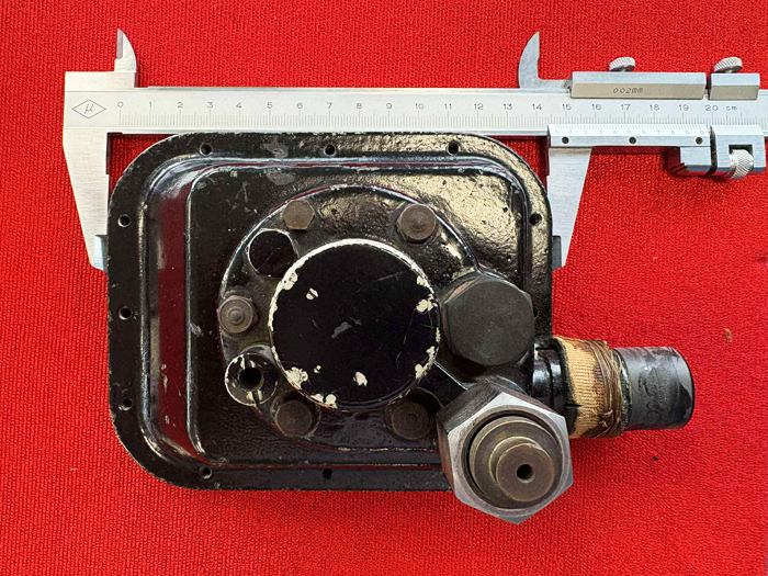
fig. 7 |
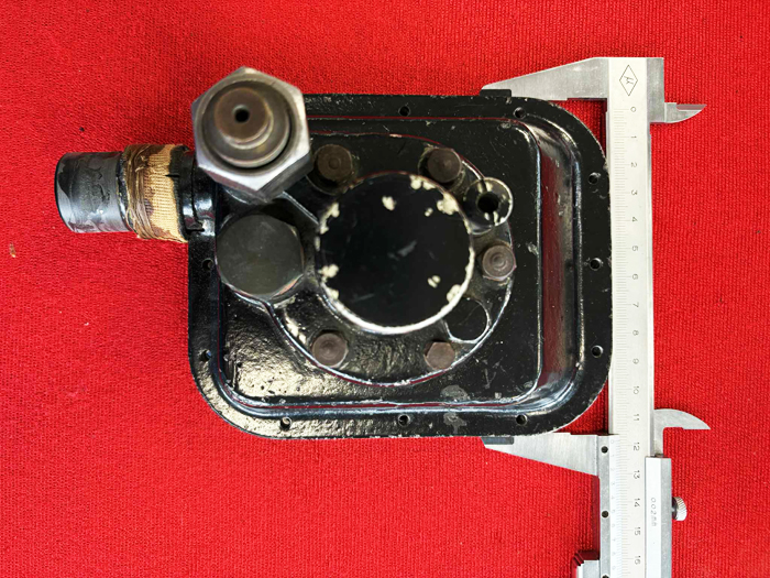
fig. 8 |
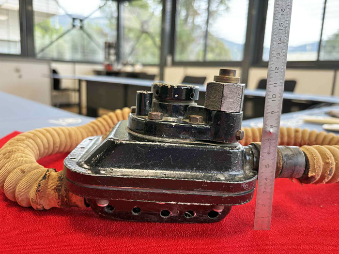
fig. 9 |
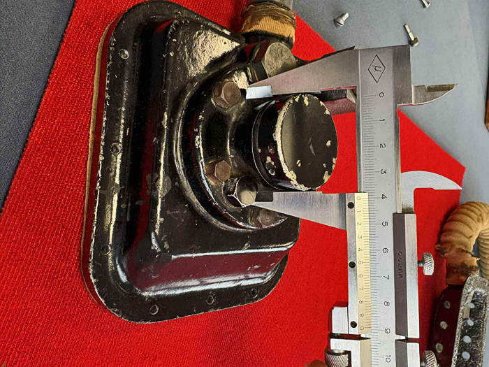
fig. 10 |
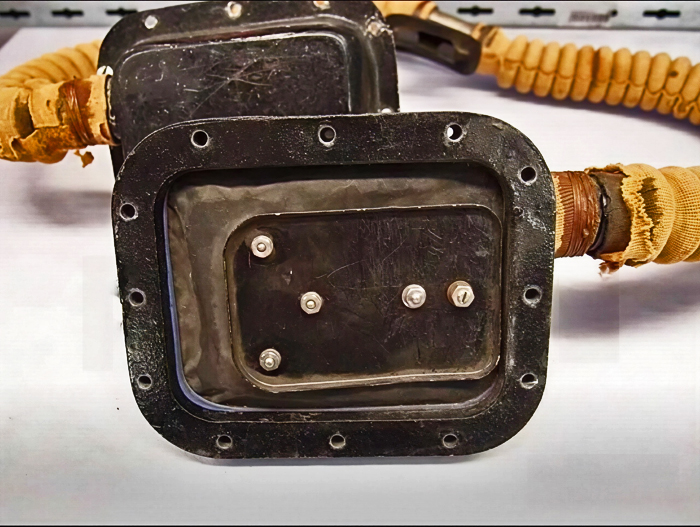
fig. 11 |
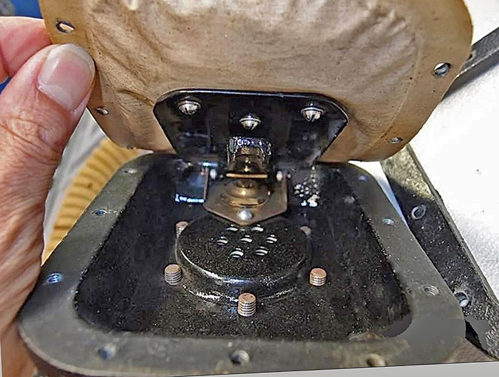
fig. 12 |
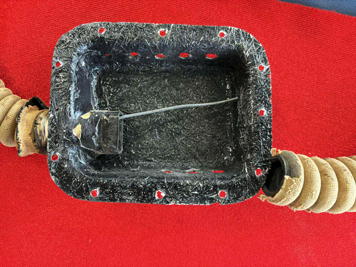
fig. 13 |
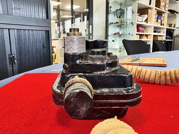
fig. 14 |
Unfortunately, it was not possible to completely disassemble the regulator to observe and measure its internal components. Aqualung, given the device's age, considers this operation risky due to the possibility of irreparably damaging some of its components (especially the rubber ones). Disassembly was therefore limited to removing the cover, an operation that nevertheless allowed us to observe some important elements of the prototype.
Some details visible in this collection of photos would seem to indicate that this unit was never used in actual pneumatic or diving tests but likely served only as a physical model conceived for the study, analysis, and verification of certain design solutions and potential industrialization processes of the device. Indeed, we note from Fig. 13 that the cover was actually made of fiberglass, a very inexpensive material and ideal for rapid prototyping but certainly not suitable for underwater use. Also note the missing duckbill exhaust valve and a metal wire that has not been removed. The latter was probably used to stabilize the metal air exhaust outlet during manual fiberglass shaping operations. In Fig. 14, it can be seen that the outlet connecting the corrugated inhalation hose even lacks a hole for air flow. Some of the hardware used to secure the various components of the device also appears oxidized, as if they were made of standard commercial components not resistant to salt corrosion. This characteristic was certainly not compatible with the intended use of this regulator.
By examining in detail the new photos of this prototype regulator and comparing them with those of the original 1943 solution, we can deduce the main modifications introduced by Émile Gagnan:
- Significant reduction in the size and weight of the regulator. This target was pretty logic considering that the initial versions of the Cousteau-Gagnan SCUBA set mainly consisted of the Air Liquide pressure reducer used in the gas fuel system of 1940s car engines. Comparing the main dimensions of the two versions, we can see that Gagnan was able to achieve a 38% reduction in frontal area. This result should have led, as a direct consequence, also to significant savings in the production costs of the device.
- Integration of the first stage pressure reduction valve within the body of the device. In the initial configuration, this component was a simple pressure reducing valve for industrial applications connected to the second stage via a rigid copper piping. Given the desired dimensions of this new version of the device and considering the air flow rates required by this application, which were certainly lower than the original industrial ones, the design of the new first-stage pressure reduction valve led to a significant downsizing of its main components. To give an idea of the extent of this miniaturization process, just consider that the diameter of the first-stage diaphragm was reduced from 65 mm in the Air Liquide industrial version to just 35 mm! Off course, all other first-stage valve components also underwent similar dimensional reductions.
- Redesign of the device cover to create a bigger internal volume and therefore more easily accommodate the duckbill exhaust valve. In the initial versions of the Cousteau-Gagnan regulator, due to the lack of space inside the second-stage cover, the exhaust valve had to be mounted outside of it (see Fig. 15) or, alternatively, it was necessary to insert spacers on the connecting screws between the cover and the second-stage body (see Fig. 16).
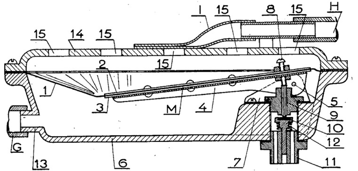
fig. 15 |
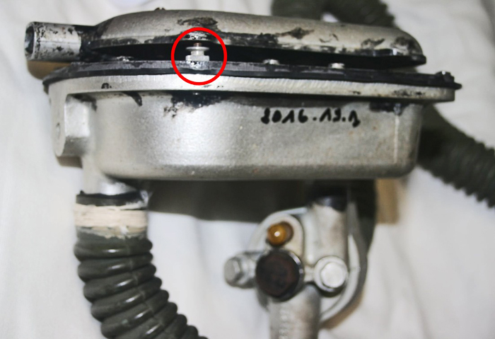
fig. 16 |
- Repositioning of the connecting inlet and outlet pipes between the second stage and the corrugated hoses in order to have a more rational setup and a shorter hoses length.
- Possibility of mounting the complete regulator directly on the air tank valve without the need for rigid or flexible connection tubes, such as those used in the initial version of the SCUBA set.
The detailed analysis of the numerous photos received from Manuel Cabrère, even without access to images and measurements of the internal parts of the device, allowed us to first create preliminary drawings of all its components and finally the complete 3D model of the regulator, as shown in Figs. 17, 18, and 19. Off course, since much information about the device's internal components was missing, we had to make some assumptions, which, however, proved perfectly compatible with both the available volumes and spaces and the expected performance of this prototype. The main assumptions established at the beginning of the 3D model development phase were the following:
- Most of the internal components of the first-stage pressure-reducing valve are identical to those of the initial production version of the CG-45. This implies that most of the miniaturization work on this important element of the device was done by Gagnan starting with this prototype. The only exception to this assumption, deduced from observing some photos of the area underneath the second-stage diaphragm (see for example Fig. 12), is the presence of 7 small springs (a central one aligned with the first-stage valve axis and 6 others placed all around the first one) used to energize the diaphragm. These 7 springs were later replaced in the production version of the regulator by a single, larger spring. Perhaps this solution, undoubtedly complex and not very economical, was initially conceived by Gagnan to reduce the overall dimensions of the first stage as much as possible.
- Use of a version of the second-stage pressure reducing valve conceptually identical to that of the Air Liquide automotive pressure reducer but slightly modified to allow for an internal air supply. This valve therefore remained an "upstream" type, as confirmed by the presence of a small max pressure safety valve installed on the bottom plate of the prototype.
- Provision of a pneumatic gauge connection port for measuring the intermediate pressure supplied by the first stage valve. This assumption is based on the presence of a threaded cap located next to the first-stage pressure reducing valve external body. The cap and the pressure safety valve are both visible in the photos of Fig. 7 and Fig. 8.
The internal functional scheme of this device, as a result of this dimensional analysis and subsequent 3D modelling work, can be observed in the various sections shown in Figs. 20, 21, 22, 23 and 24.
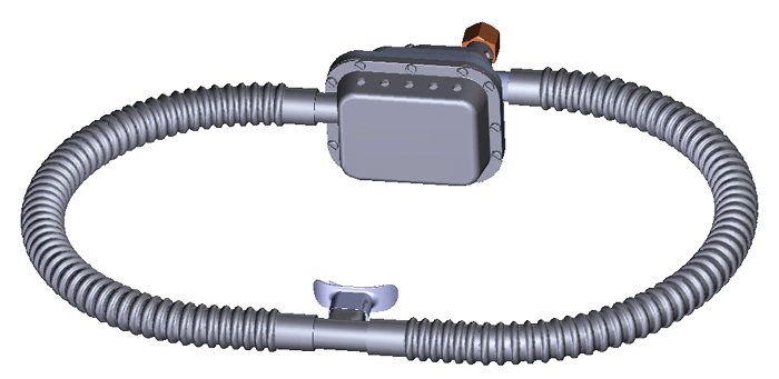
fig. 17 |
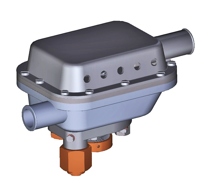
fig. 18 |
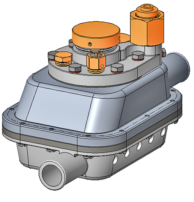
fig. 19 |
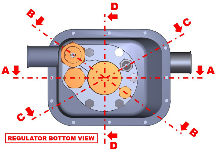
fig. 20 |
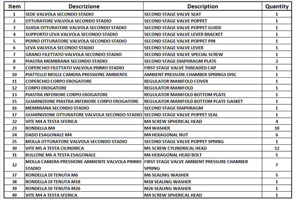
Section A-A of Fig. 21 (see the list of components referred to in this section in Table 1) shows the complete functional scheme of the device with its main mechanical components and the pneumatic connections between the first and second stage valves. The section also shows the second stage diaphragm with its “upstream” valve actuation system.
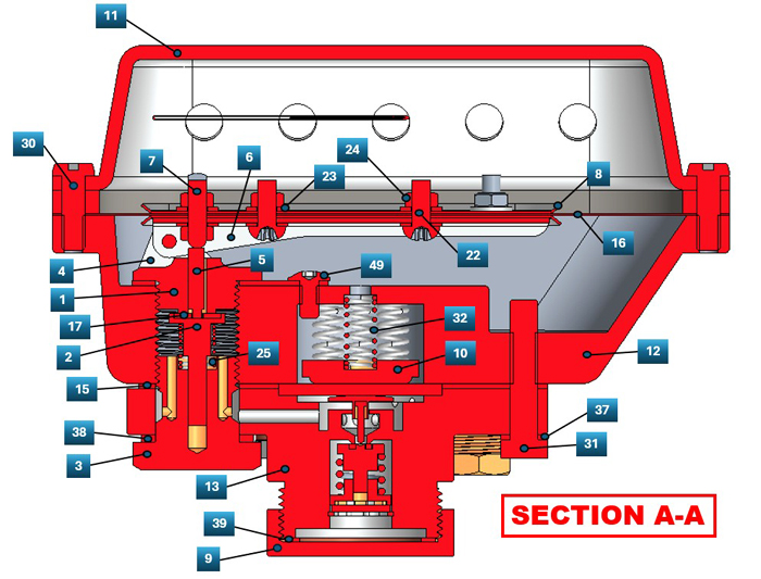
fig. 21 |
TAB. 1
Section B-B of Fig. 22 (see the list of components referred to in this section in Table 2) mainly shows the pneumatic internal piping between the connection with the air tank valve and the first stage pressure reducing valve. Moreover, the pneumatic line designed for measuring the intermediate pressure downstream of the aforementioned valve is represented.
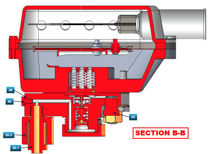
fig. 22 |

tab.2 |
Section C-C of Fig. 23 (see the list of components referred to in this section in Table 3) shows the connection between the first stage pressure reducing valve outlet and the max pressure safety valve.
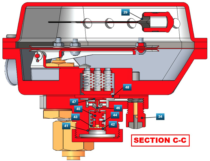
fig. 23 |
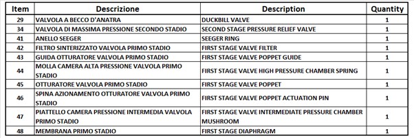
tab. 3 |
Finally, the D-D section of Fig. 24 (see the list of components referred to in this section in Table 4) shows the complete cross-section of the regulator.
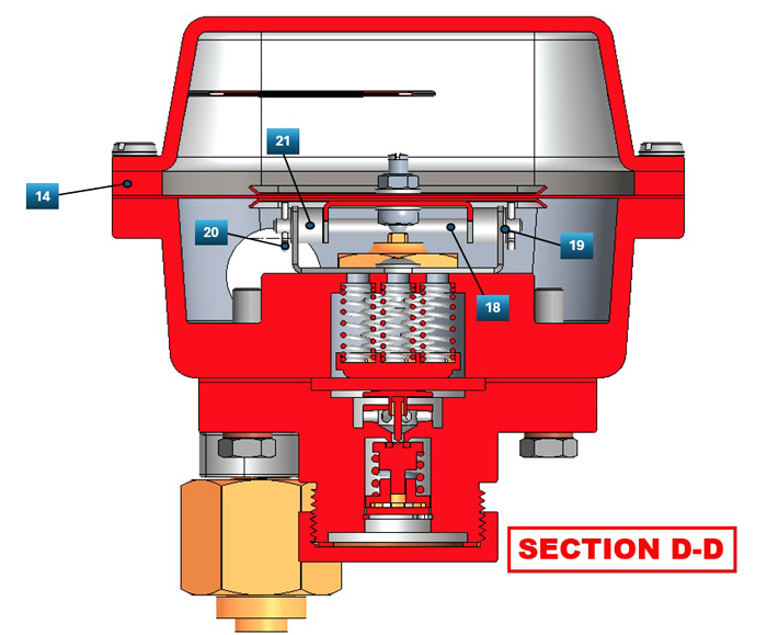
fig. 24 |

tab. 4 |
The three-dimensional CAD models were then used to generate PDF manufacturing drawings for the parts to be produced through mechanical machining, and STL files for those components to be 3D printed.
Choosing the optimal 3D printing method for this project required a very deep analysis, as there were design needs and requirements that were difficult to meet with a single specific printing process. In this case, some parts to be printed required considerable precision and the need to reproduce highly detailed construction elements with very tight tolerances (for example, some threads realized directly into the print and the cavities for mounting the first-stage valve components). The external surfaces of the parts also needed to have a good finish without the need of long and tedious filling and smoothing operations. Finally, good mechanical strength was also desirable, especially in areas where springs, screws, bolts, and other threaded elements would later be installed.
After various trials and attempts, we opted for the "resin" printing process, which was able to fully satisfy all the requirements except mechanical strength. We would then determine during the final assembly of the replica whether this strength would be sufficient for our purposes. The components printed using this process are shown in Figs. 25, 26, 27, and 28.
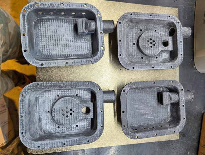
fig. 25 |
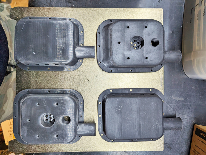
fig. 26 |
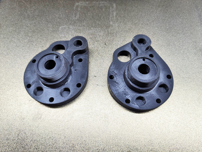
fig. 27 |
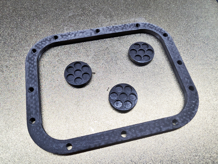
fig. 28 |
These parts would then be threaded (where required) and finally lightly sanded before being painted. The disks with the seats for the seven springs of the first-stage valve diaphragm (see Fig. 28) would also be machined from brass.
The metal components made from mechanical machining processes were primarily those of the first- and second-stage pressure reducing valves. The chosen construction material was brass (see Fig. 29), as was done in the previous project for the CG-43 replica. Other components used in the various actuation mechanisms of the device (e.g., pins, threaded grain, springs) were made from stainless steel (see Fig. 30).
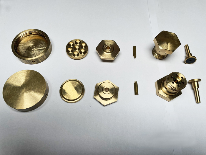
fig. 29 |
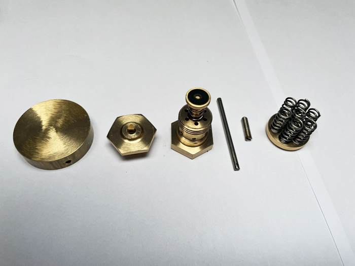
fig. 30 |
The main parts of the second-stage valve actuation mechanism were produced from laser-cut and then bent stainless steel sheets (0.5 and 1 mm thick) (see Fig. 31). The parts were then painted black as in the original prototype (see Fig. 32).
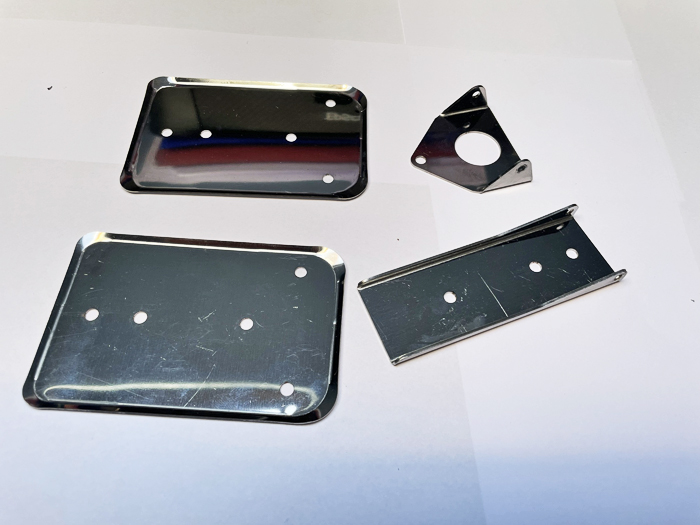
fig. 31 |
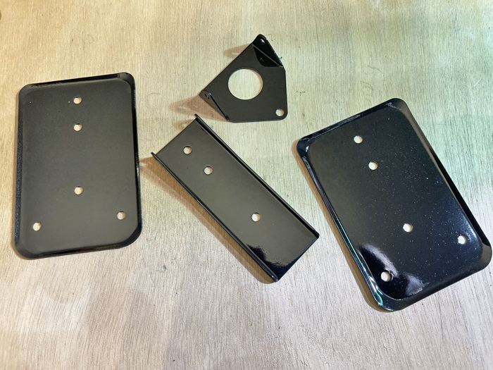
fig. 32 |
The second-stage diaphragm and the special flat gasket (the latter located between the lower surface of the regulator body and the base plate containing most of the pneumatic circuit components) were made using punches (of the same diameter as the holes to be made) and simple scissors. The exact position for the punches and the correct external cutting profile were indicated by applying and fixing a 1:1 paper print of the diaphragm and gasket to the base sheets to be worked (see Figs. 33, 34, and 35). The complete set of tools used during this process is shown in Fig. 36. The diaphragm was made from a 0.5 mm thick sheet of black silicone rubber, while the gasket was manufactured using a 1 mm thick sheet of AFM 37/8, a material specifically designed for the production of flat gaskets used in the assembly of internal combustion engines and other similar applications.
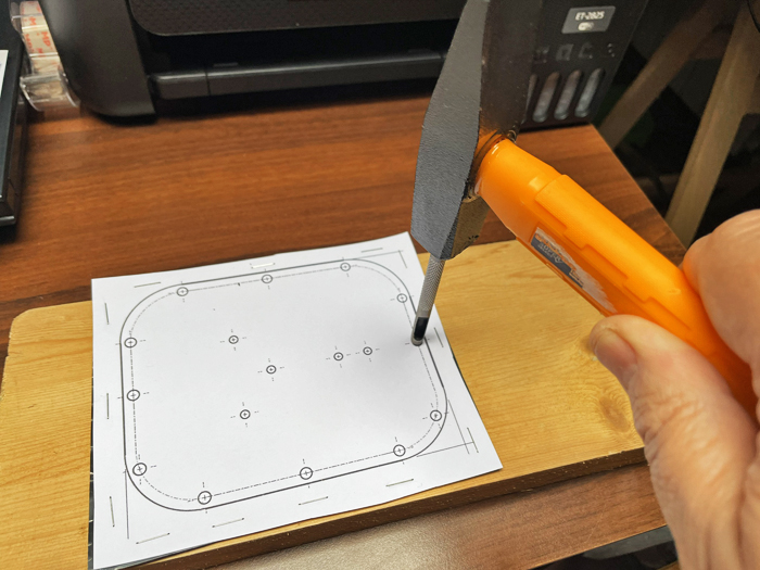
fig. 33 |
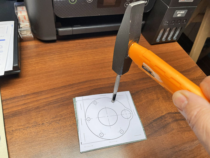
fig. 34 |
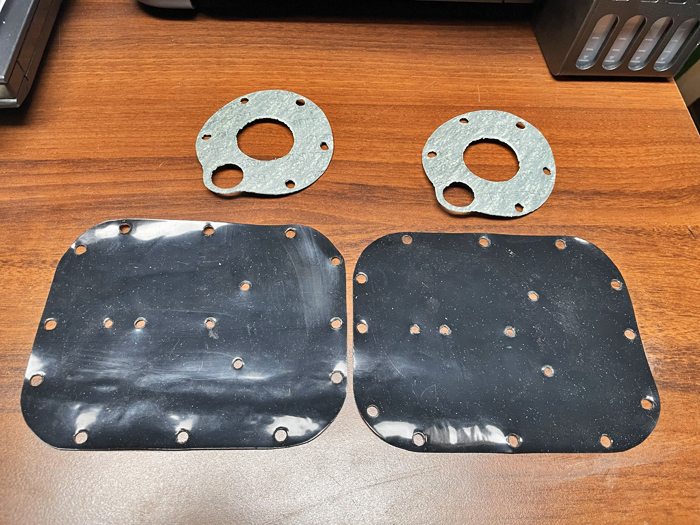
fig. 35 |
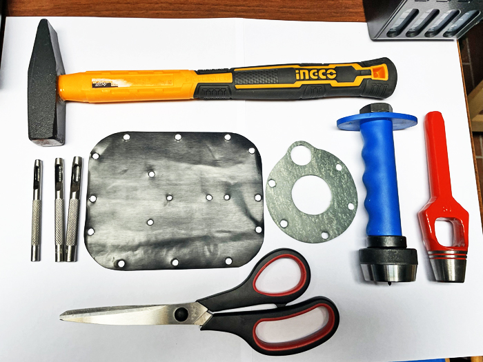
fig. 36 |
Other fundamental components for the construction of this replica were found online such as the adapter according to the DIN 477 standard for connection to the air tank valve (see Fig. 37) and the brass plug installed on the pressure gauge port for controlling the intermediate pressure (see Fig. 38).
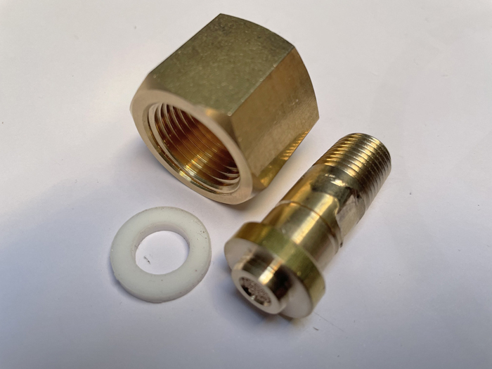
fig. 37 |
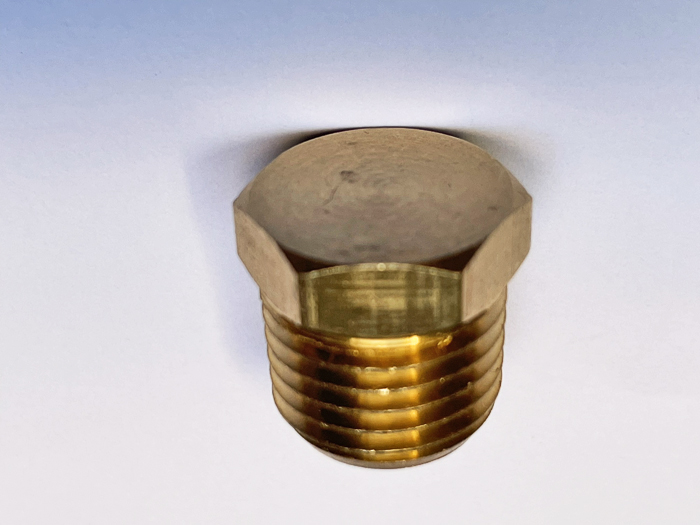
fig. 38 |
The max pressure safety valve mounted downstream of the first stage pressure reducing valve (see Fig. 39) was obtained from one of the industrial-type pressure regulators I had purchased as part of the previous project of the CG-43 prototype replica rebuilt. Note that all three components described above have a 1/4 NPT (60°) tapered thread with a 1/16 inches pitch, which was and still is the standard for this type of connection. The mouthpiece's "T" terminal was already available among the materials in my spare parts stock. In fact, this appears to be identical in geometry to the one used in the early versions of the Mistral regulators (see Fig. 40). The surface treatment is probably not the same, but this was considered not essential for the purposes and limitations of this project.
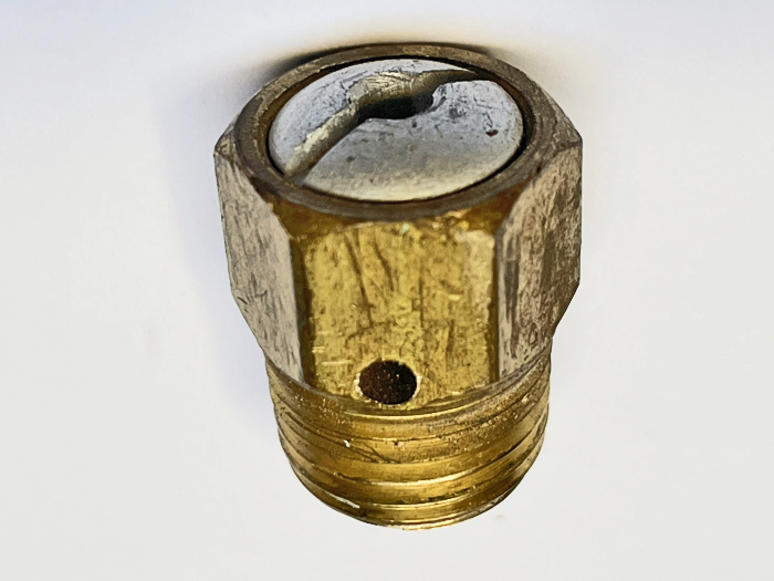
fig. 39 |
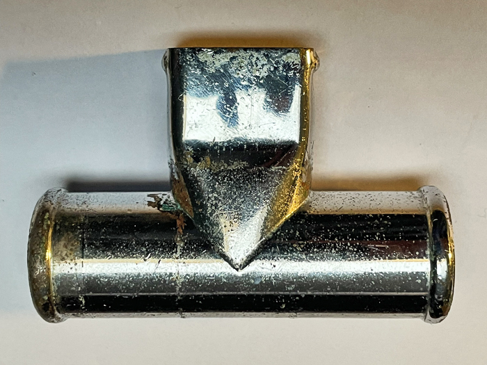
fig. 40 |
All the other materials needed to complete the replica were also located and purchased online. These components, which include screws, bolts, copper washers, nuts, spacers, cotter pins, etc., were found through to a long and boring search of the many websites selling these types of items. After gathering all the materials, the final assembly process began, first for the several subassemblies and finally at the complete device level.
We began by mounting the corrugated hoses and the rubber mouthpiece on the "T" terminal described above. The fabric-covered corrugated hoses are the same type as those used in the construction of the CG-43 replica, while the rubber mouthpiece was 3D-printed for a previous project. Again, the fastening system chosen (clearly visible on the original prototype) was copper wire covered with self-vulcanizing rubber tape (see Figs. 41 and 42).
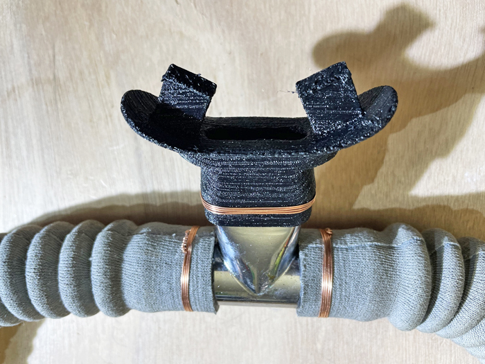
fig. 41 |
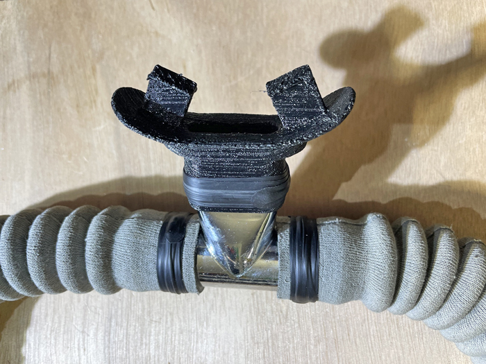
fig. 42 |
After finishing and final painting, the regulator cover was completed with the duckbill valve assembly, which was then secured using the usual copper wire clamping method (see Fig. 43).
The base plate, designed to contain most of the first-stage valve components and the whole pneumatic circuit of the device, was fitted with the air tank DIN 477 connection adapter, the max pressure safety valve, and the pressure gauge port plug (see Fig. 44).
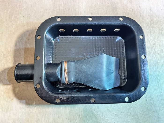
fig. 43 |
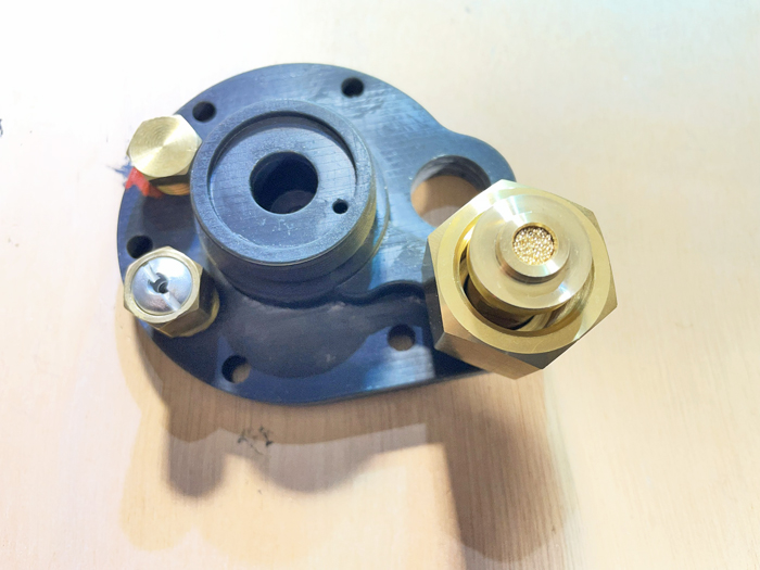
fig. 44 |
After installing the threaded circular cap at the inlet of the first-stage pressure reducing valve and protecting by paper tape the air tank DIN 477 connection adapter (this component was not painted even in the original prototype), the complete base plate assembly was painted black (see Fig. 45). Some of the internal components of the first-stage pressure-reducing valve (see Fig. 46) were provided directly by Luc and I, taking them from our spare parts stocks for the CG-45 regulators and their derivatives.
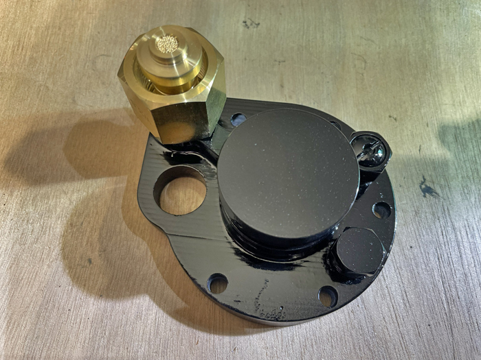
fig. 45 |
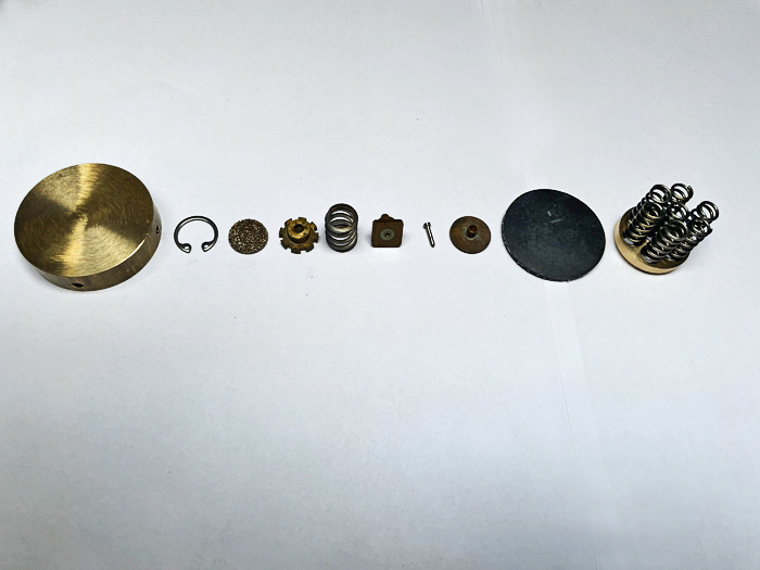
fig. 46 |
All these parts were then installed inside the base plate and the regulator body (after this second component was also finished and painted), as shown in Figs. 47, 48, 49, 50, 51 and 52.
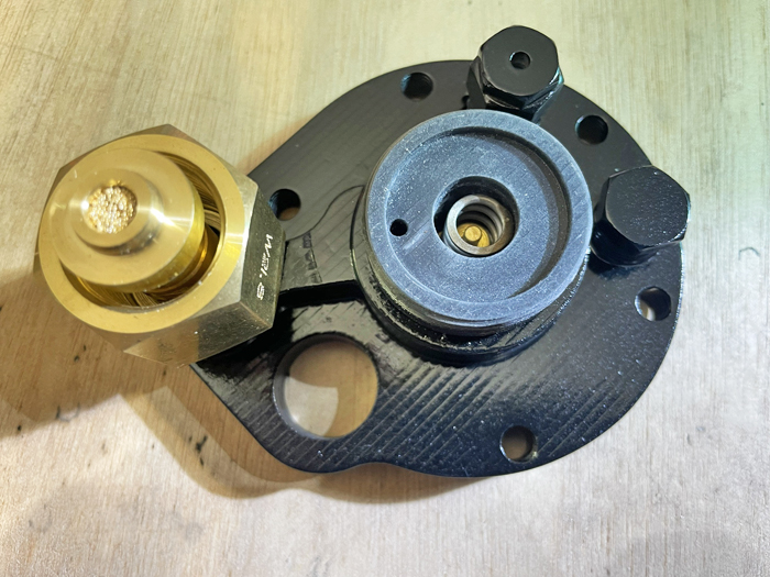
fig. 47 |
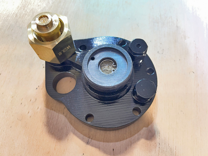
fig. 48 |
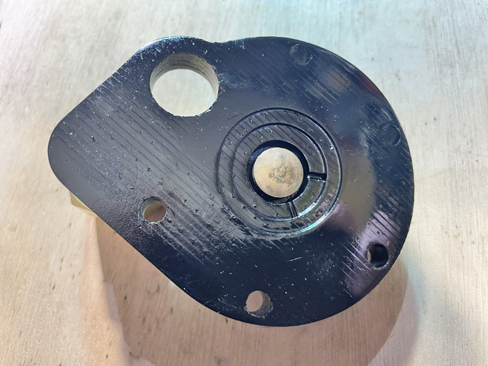
fig. 49 |
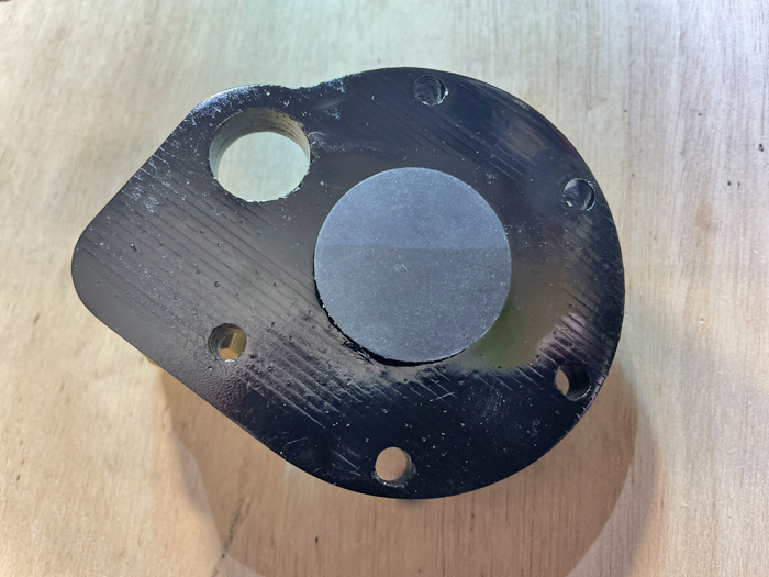
fig. 50 |
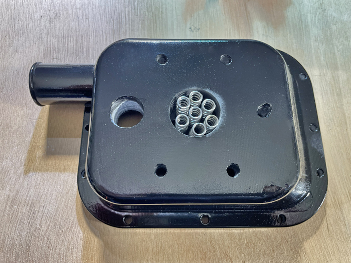
fig. 51 |
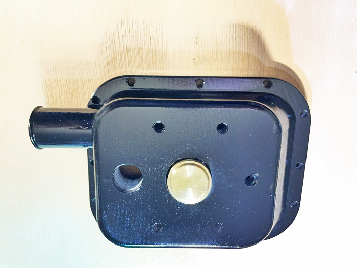
fig. 52 |
At this point the top cap of the second stage valve was mounted, which also acts as a guide for the triangular cross-section actuating pin, and its actuating lever (see Figs. 53 and 54).
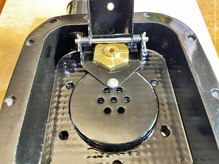
fig. 53 |
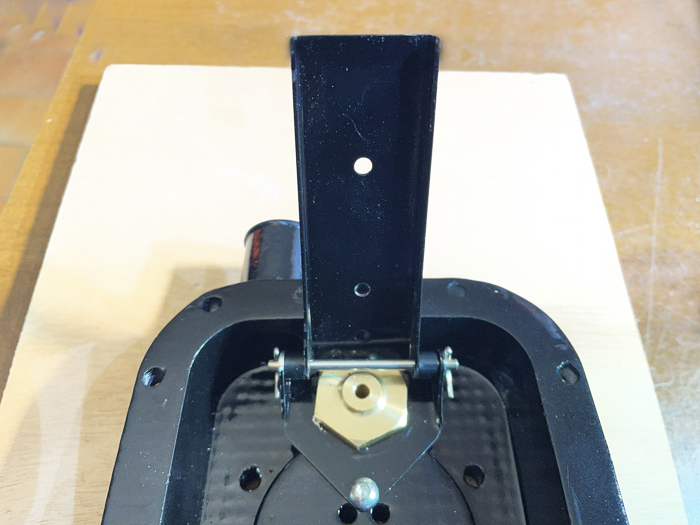
fig. 54 |
We have now completed the mounting of the second-stage diaphragm assembly, including the threaded grain used to adjust the relative position of the lever and the second-stage valve actuation pin (see Fig. 55).
The next step was to install the flat gasket between the base plate and the body of the regulator, also by inserting the five M6 bolts connecting these two elements (see Fig. 56).
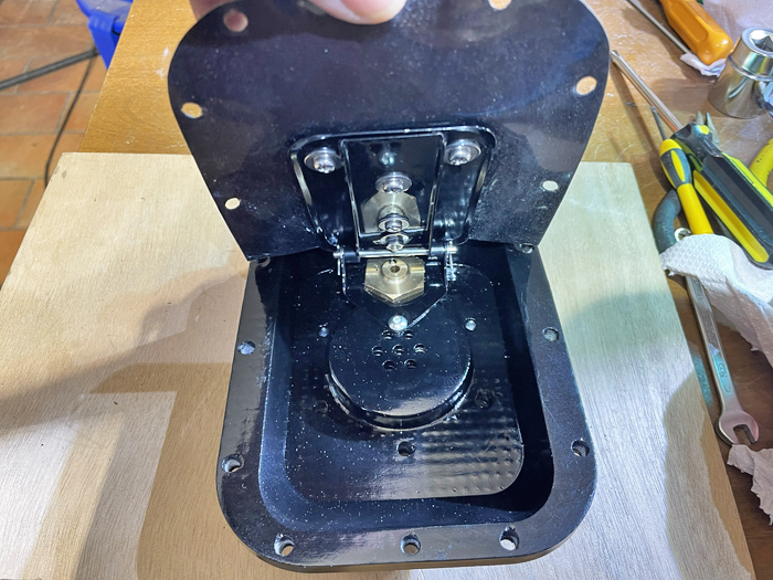
fig. 55 |
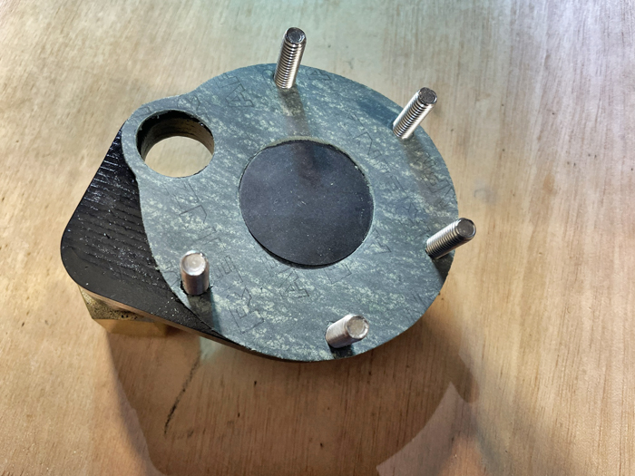
fug. 56 |
The base plate was then mounted on the lower face of the regulator body, as shown in Fig. 57. Subsequently, the lower part of the second stage valve, complete with poppet and spring, was also inserted and tightened (see Fig. 58).
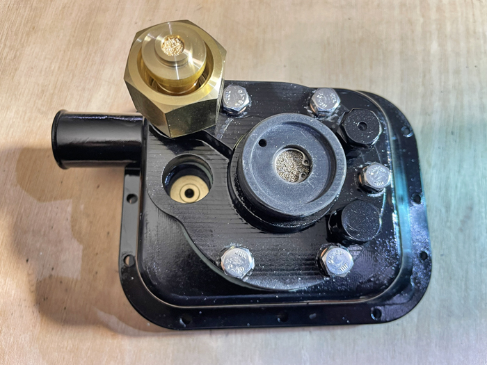
fig. 57 |
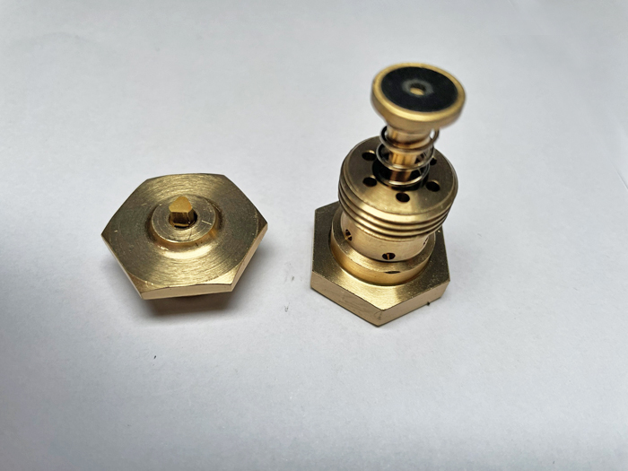
fig. 58 |
With the second stage valve fully assembled, the triangular section pin was then inserted (see Fig. 59) and finally the final adjustment of the lever position was made. This adjustment must allow the second stage diaphragm to be completely aligned and coplanar with the external frame of the regulator body (see Fig. 60).
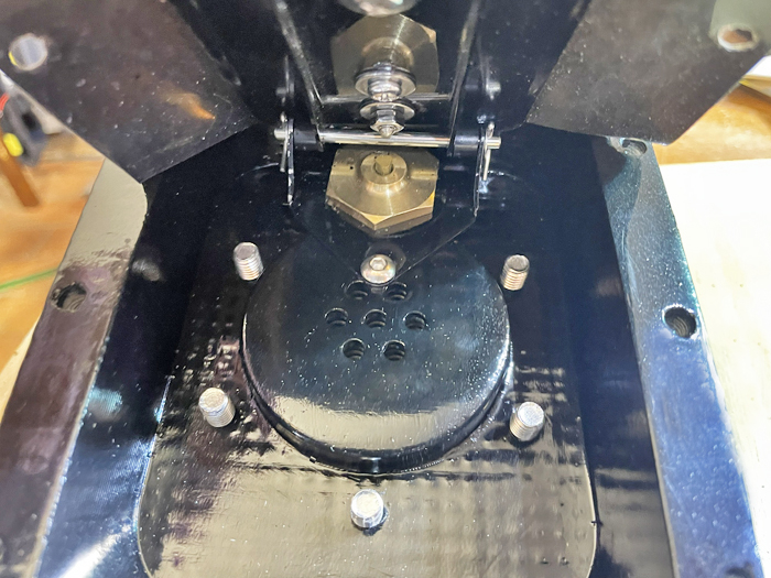
fig. 59 |
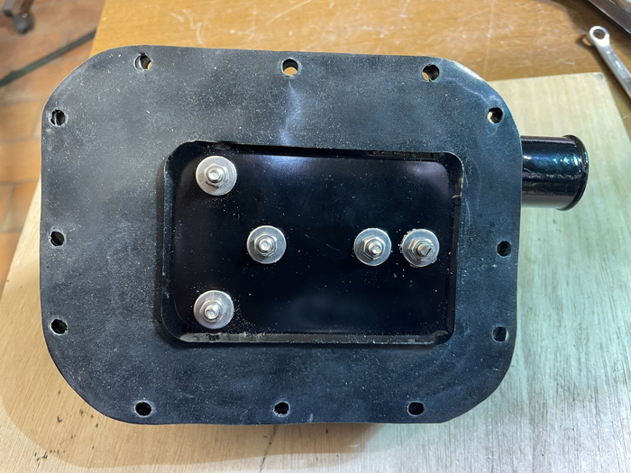
fig. 60 |
The complete assembly of the regulator body was then completed with the installation of the cover (connected to the body by 12 M5 stainless steel screws, as shown in Fig. 61) and the threaded cap closing the first stage valve inlet (see Fig. 62).
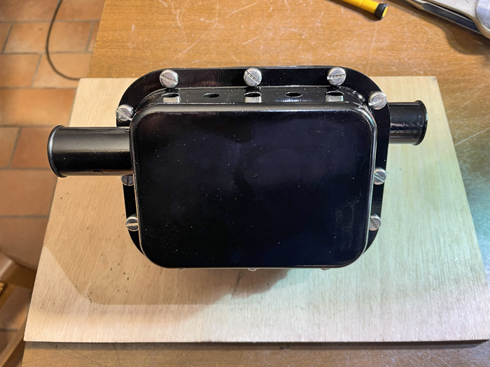
fig. 61 |
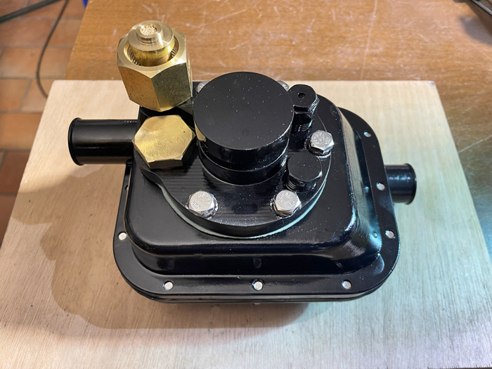
fig. 62 |
The resulting body was now ready to receive the corrugated hoses, the mouthpiece and the nozzle that had been assembled previously. In this case, too, the hoses were tightened onto the inlet and outlet pipes provided in the body of the device using copper wire, which was then covered with rubber tape (see Figs. 63 and 64).
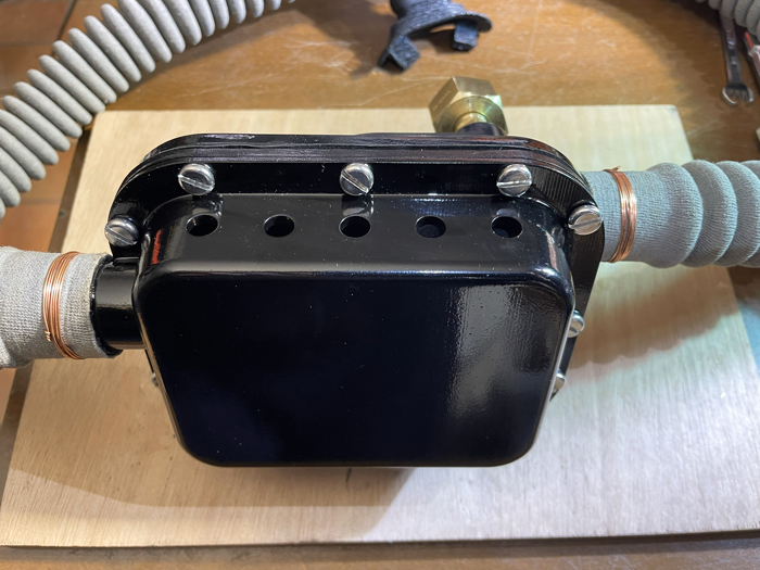
fig. 63 |
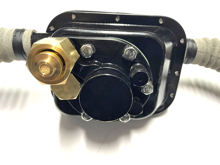
fig. 64 |
With this final assembly phase, the replica is definitively completed as shown in Figs. 65, 66, 67, 68 and 69. Finally, this sample also found its place inside one of the display cases of my small museum in Gubbio dedicated to historical diving equipment (see Fig. 70).
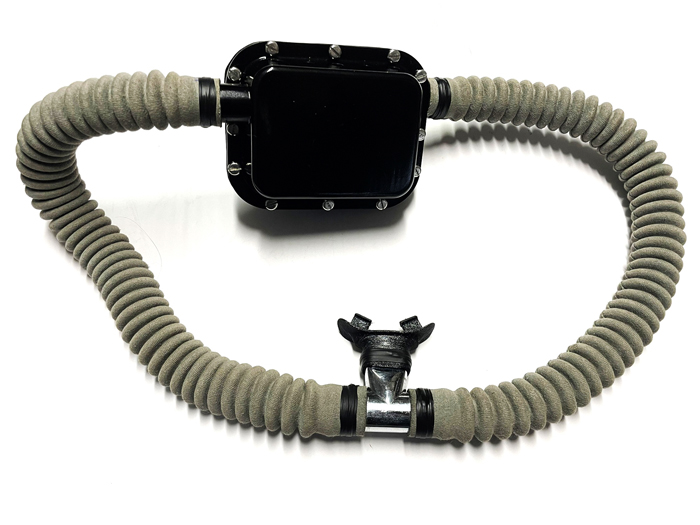
fig. 65 |
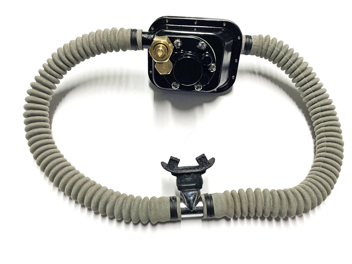
fig. 66 |
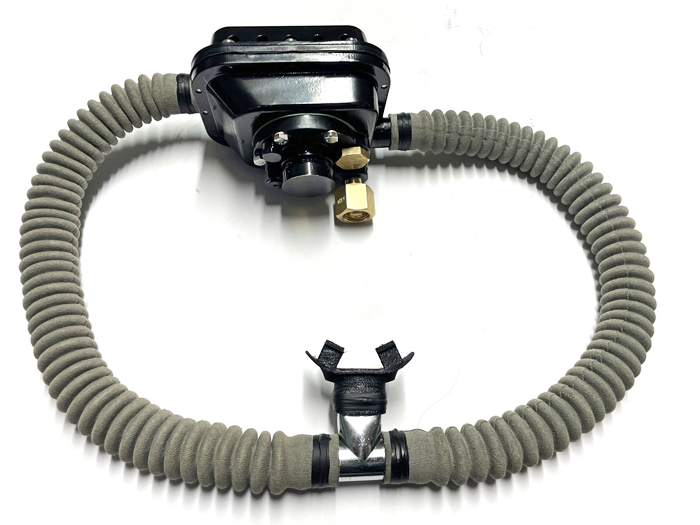
fig. 67 |
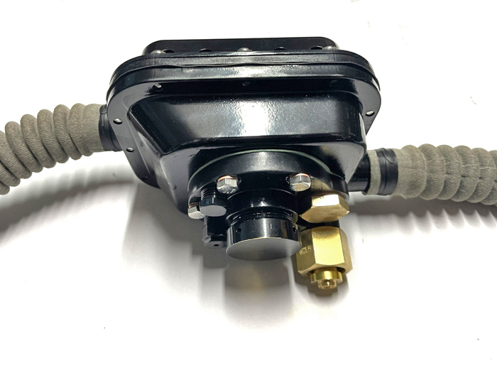
fig. 68 |
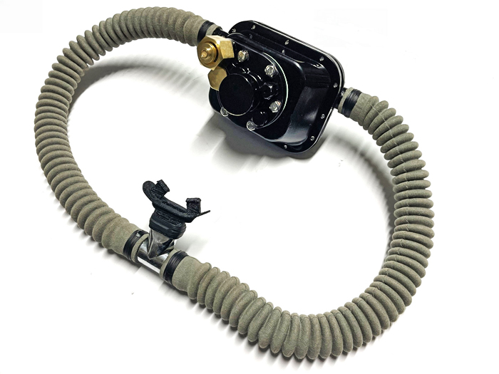
fig. 69 |
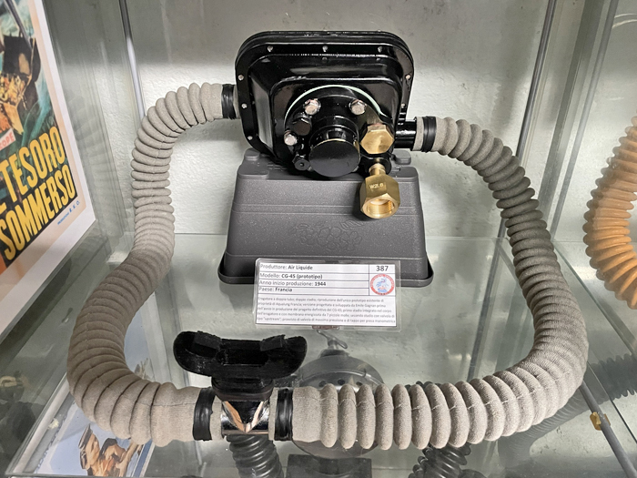
fig. 70 |
To conclude this second article, I would like to point out that, even with all the updates introduced in this new version compared to the original one from 1943, Gagnan was not satisfied with the results achieved and so continued his work on improving the device, despite the difficulties and limitations experienced during the final phase of the war. The regulator in fact saw a further evolution at the end of 1945 with what would be the initial production configuration, a phase started the following year (1946) with the creation of La Spirotechnique (see Figs. 71 and 72).
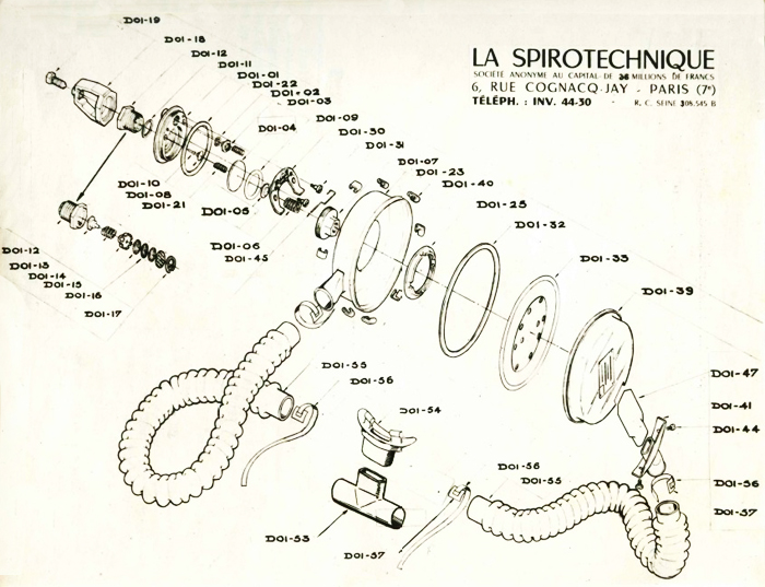
fig. 71 |
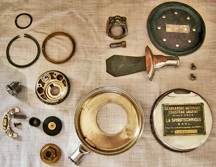
fig. 72 |
This version would undergo further updates in the following years by Gagnan, especially after he moved to Montreal, Canada, in 1947 to work for the Canadian subsidiary of Air Liquide. The French engineer always had a clear goal of further reducing production costs and improving the device's performance.
The main modifications that Gagnan subsequently introduced to the CG-45 configuration, before the start of production, were the following:
- Transformation of the regulator body from a rectangular to a circular shape. This modification also allowed for more effective use of the second stage diaphragm, which was also circular and could therefore operate along the regulator's axis, so improving its sensitivity. This change in geometry was also accompanied by new solutions in terms of materials and production processes used. The die-cast aluminum used in manufacturing of both the Air Liquide automotive pressure reducer and the lower half of the body of this prototype, was replaced by brass sheet. This material was first cut and then cold drawn to obtain the two characteristic half-shells making the body of the new regulator. This solution, in addition to drastically reducing manufacturing costs, was much more effective in improving the device's corrosion resistance, especially during operations in salt water. In fact, all the brass parts of the new version (making the vast majority of the device) were effectively protected by surface treatments such as chrome or nickel plating. These processes would become the standard for these devices in subsequent years. The use of aluminum in saline environments, even when subjected to protective treatments (e.g., galvanic oxidation), revealed all its limitations due to the phenomenon of electrochemical corrosion. This process occurs whenever the material comes into contact with different metals used in the manufacturing of the regulator other components.
- Complete redesign of the second-stage valve, moving from the "upstream" configuration, typical of industrial pressure reducers, to a "downstream" one, which eliminated the max pressure relief valve. This new valve prevented the risk of over-pressurization of the regulator's low-pressure circuit, which could cause a failure in case of the first-stage valve leaking. During this redesign, Gagnan also sought to improve the device's breathing performance by significantly increasing the airflow cross-sections in the low-pressure circuit.
- Modification of the second stage valve actuation lever, which now took on the characteristic “horseshoe” shape. This geometry allowed the lever to be actuated by the diaphragm in its central position without interfering with the first stage mechanism.
- Simplification of the first stage diaphragm precompression system which now became of a single spring type, thus abandoning the solution tested on the prototype which used 7 smaller springs, acting in parallel.
- Complete redesign of the air tank valve connection, which was now placed on the same axis as the first-stage valve and at its inlet. This solution, which consisted of a simple yoke with a yoke bolt (which would later become a handwheel yoke screw in subsequent versions), allowed the direct connection between the air tank valve outlet and the regulator first-stage valve inlet.
- Modification of the regulator cover with the introduction of an easily removable exhaust pipe provided with two screws. This solution allowed for easier replacement of the duckbill exhaust valve.
- Drastic reduction in the number of connecting elements for the various parts of the regulator. The 12 screws connecting the cover to the body of the prototype and the 5 bolts installed between the body and the base plate would be reduced to a total of just 4 screws and 1 bolt. To connect the two halves of the new regulator’s body, Gagnan opted for a system based on 7 small C-shaped clips.
This article concludes my work of rebuilding the replicas of the two known and still existing prototype versions of the Cousteau-Gagnan breathing apparatus. This project lasted several months, from May 2025 to January 2026. It was a difficult but extremely stimulating and rewarding challenge, with many different yet crucial moments for the success of the project. Long months were dedicated to researching data, photos, and information on the prototypes to be rebuilt, to technical analysis and feasibility studies, to defining the dimensional characteristics of the parts and creating 3D models, to searching online for the necessary materials, to contacting mechanical machining shops and 3D printers, to the finishing, painting and assembly performed in my small home workshop, and finally, to writing these two articles.
At the end of this adventure, I can confidently say that, in addition to significantly increasing my historical knowledge of the evolution of this device through the identification and study of many documents of those times, this work has enabled me to develop and refine effective techniques and methodologies for reconstructing this type of equipment. This knowledge, I hope, will be useful to all enthusiasts and collectors who wish to undertake this type of efforts. It is a wealth of knowledge and experience that I am happy to share with all of them. It was also a true team effort, with information, data, photographs, and documents gathered and shared by two collectors of different nationalities, both strongly motivated to achieve a common goal, free from jealousy, hesitation, or reticence. Each of us contributed the best of our knowledge and skills. And, ultimately, it is a sincere tribute to the incredible adventure that was the birth of self-contained recreational diving, an event that owes much to the genius of Émile Gagnan.
_______________