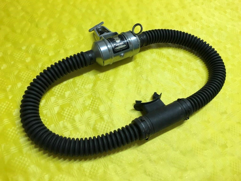
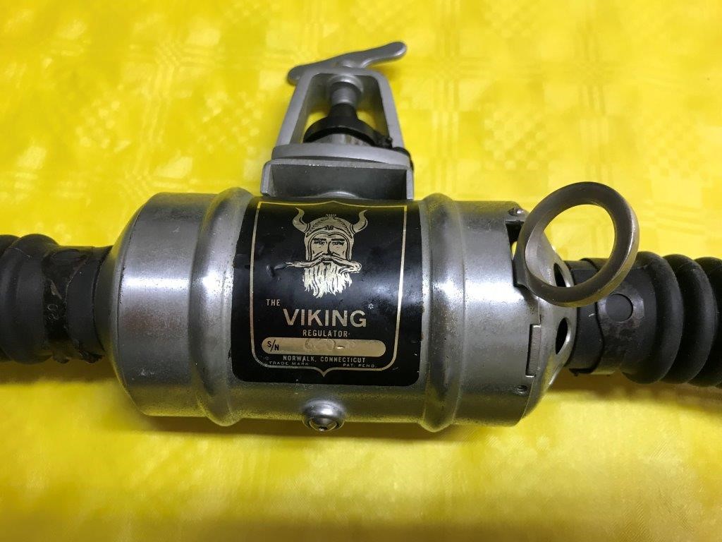
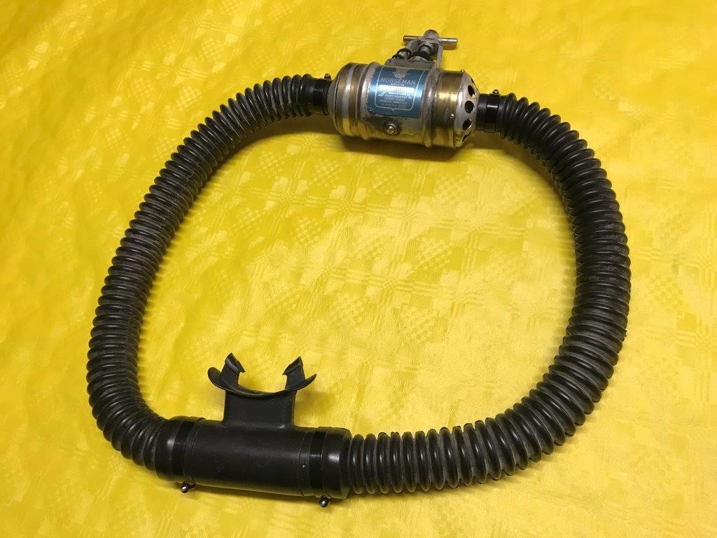
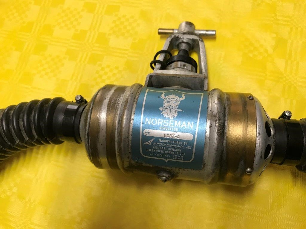
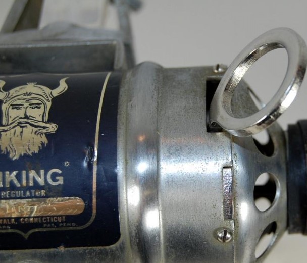
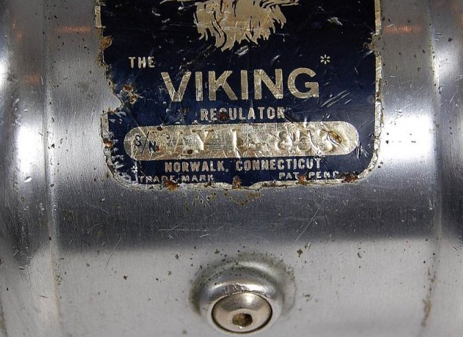
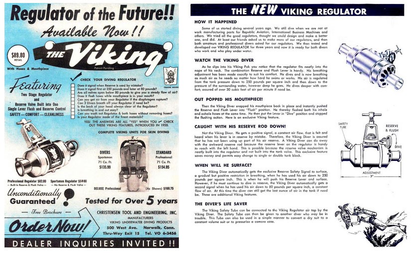
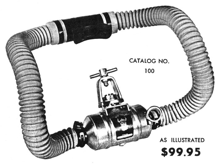
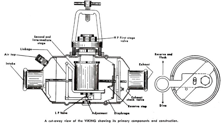
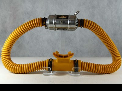
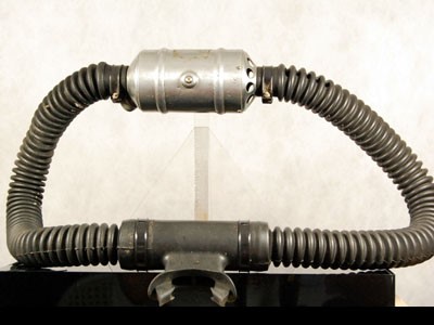
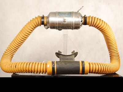
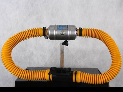
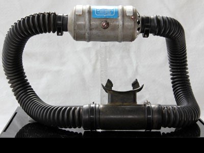
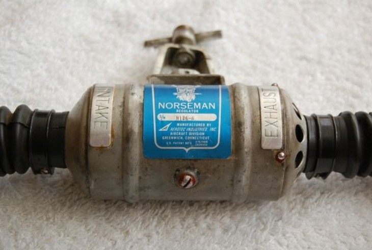
In the universe of inventions and technical proposals, more or less eccentric, which bloomed during the ’50 years, due to the pioneers and to the former diving gear industries, following the success and the great interest raised by the Cousteau-Gagnan regulator, a place of honor is definitely deserved to the “Viking” double hose regulator, manufactured by Christensen Tool and Engineering Inc. from Norwalk, Connecticut, from 1958 to 1960 (see Fig. 1 and Fig. 2) and to its successor “Norseman”, built by Aerotec Industries Aircraft Division from Greenwich, Connecticut, from 1961 to 1963 (see Fig. 3 and Fig. 4).
 |
 |
| Fig. 1 | Fig. 2 |
 |
 |
| Fig. 3 | Fig. 4 |
Precisely, for the unique shape of their main bodies, these two stages regulators were named “beer can” by the insiders.
The main concern the designers had at that time was to invent something not violating one of the patents owned by Emile Gagnan, some time together J. Y. Cousteau, like for the CG-45 and Mistral regulators, who had behind the financial and commercial power of La Spirotechnique initially and of the controlled U. S. Divers later. It was almost hopeless a model in production, having characteristics similar to those of the products coming from the two companies said before, could have survived in case of legal conflicts with such companies.
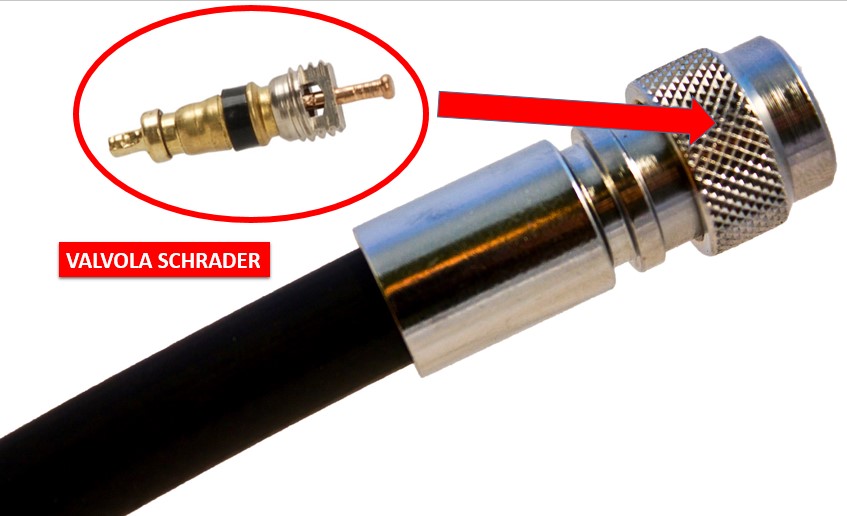
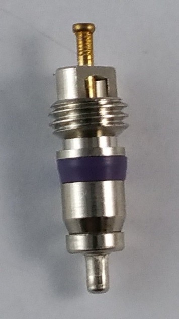
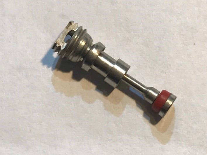
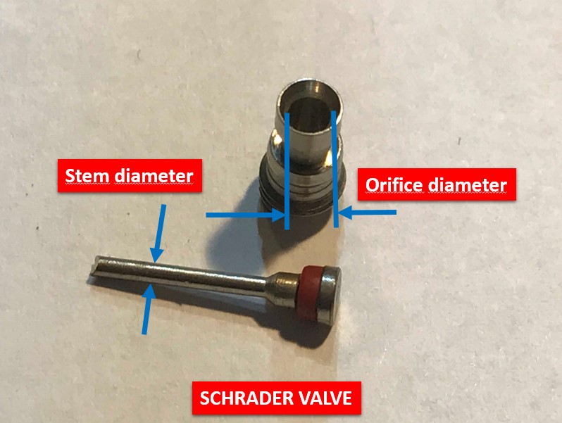
This limitation was indeed very clear to the designer James P. Fay when he had that he believed to be the brilliant idea capable to solve the potential conflict with the Cousteau-Gagnan patents and, at the same time, to ensure outstanding performances to his inventions. The Fay’s ”Columbus’ egg” was the “Schrader valve” (see Fig. 5), namely the small valve we well know still nowadays to be used for tires pressure inflating but also in the current BCD’s VIS inflating hoses (see Fig. 6).
|
|
 |
| Fig. 5 | Fig. 6 |
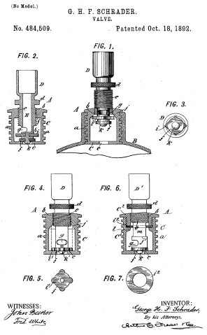
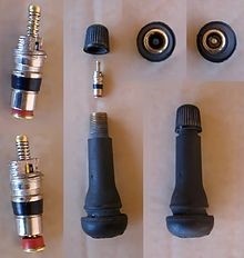
La valvola Schrader rappresenta indubbiamente una delle soluzioni tecniche più brillanti mai concepite visto che, a distanza di più di 120 anni dalla sua invenzione (vedi Fig. 7), è ancora ampiamente utilizzata nel mondo industriale (vedi Fig. 8).
 |
 |
| fig. 7 | fig. 8 |
Using this valve, Fay turned up having available, in large quantity and at the lowest cost, the basic components of his regulators, whose pressure reducing stages were based precisely on this small valve. Another advantage offered by the Schrader valve consisted in its small activation force, a force allowing the regulator’s air flow start-up, also with limited diver’s inhaling effort and with a pressure balancing diaphragm having a surface much smaller than that of the Aqualung.
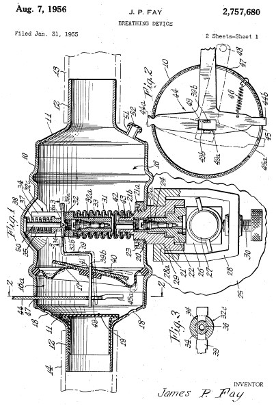
Fay felt in love with this small valve at an extent pushing him to even present and deposit four patents, each of the based on the use of this fundamental component. The first of those patents, number 2.757.680 (Fig. 9), filed on January 31st 1955, already introduced the “beer can” typical cylindrical shape of the regulator’s body and used two Schrader valves, one in the first stage and another one in the second stage.
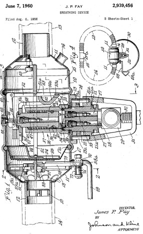
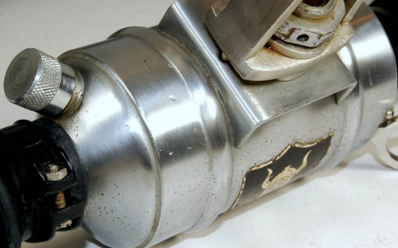
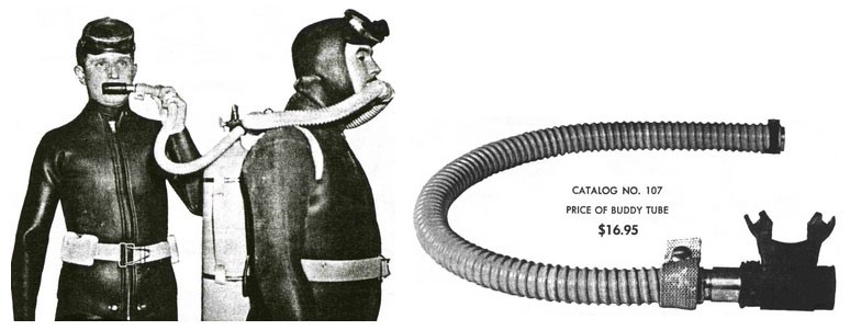
The second patent, number 2.939.456 (Fig. 10), filed on August 6th 1956, would have been that of the Viking’s prototype version with three Schrader valves, two located in parallel in the first stage and one in the second stage. Of this model that patent already included other peculiar features. These were the dive-flushing switching lever (see Fig. 11), the air-flow start-up sensitivity adjusting screw (see Fig. 12) and the coupling for a buddy emergency air supply device (see Fig. 13 and Fig. 14). This latter feature remained a unique characteristic of this model among all the other double hose regulators.
 |
 |
| fig. 9 | fig. 10 |
 |
 |
| fig. 11 | fig. 12 |
 |
| fig. 13 |
 |
| fig. 14 |
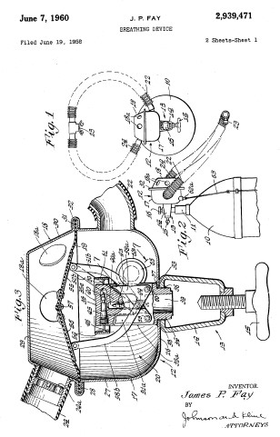
The third patent, number 2.939.471 (Fig. 15), filed on June 19th 1958, had the aim to be a variant of the previous patents. This, although still using the Shrader valves as main functional elements of the pressure reducing stages (in this case three valves for the first stage and one for the second stage), proposed a more conventional shape for the regulator’s main body. Therefore, according to his expectations, this shape was to receive more appreciation from the divers’ community already familiarized with the aesthetic contents of the Aqualung.
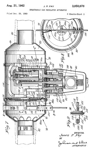
His last patent, number 3.050.076 (Fig. 16) filed on December 29th 1960, in addition of another configuration never put in production, described a simplified solution with respect to that used in the Viking, without the air-flow start-up sensitivity adjusting screw and the coupling for a buddy emergency air supply device.
 |
 |
| fig. 15 | fig. 16 |
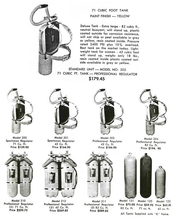
The first prototypes of the Viking were manufactured in 1954, one year before James P. Fay filed the first of his patents. As a normal practice in the USA also in the following years, on middle of 1955 the NEDU (Navy’s Experimental Diving Unit) carried out some tests on prototypes of this regulator. These tests highlighted some functioning and performance issues which will be described later. Fay, with the support of the professional diver George Swindell, introduced some modifications to the design in such a way to solve the issues reported by the NEDU. In 1958, thanks to Christensen Tool and Engineering Inc. from Norwalk, Connecticut, the production and distribution phases of this regulator started. The regulator was supplied with several configurations of air tanks, backpacks and harness, as shown in the advertising leaflets of that time (see Fig. 17, Fig. 18, Fig. 19, Fig. 20 and Fig. 21).
 |
| fig. 17 |
 |
 |
| fig. 18 | fig. 19 |
 |
 |
| fig. 20 | fig. 21 |
Unfortunately, despite the thoughts and the expectations of the inventor, this regulator showed remarkable performance and reliability problems, in addition to calibration and maintenance difficulties. These problems caused its commercial failure and a production volume limited to 2500-2600 units, for the Viking, and to approximately 450 units, for the Norseman.
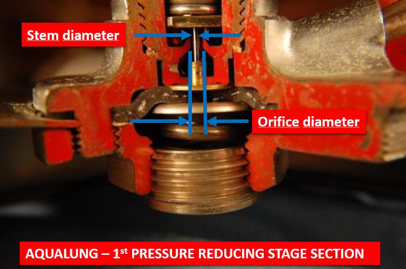
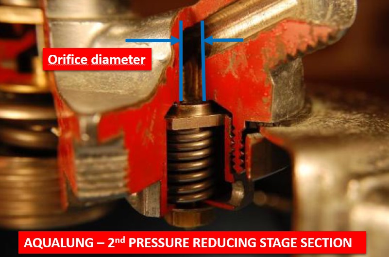
The main reason of this flop was precisely the selection of the Schrader valve, as pressure reducing device. We will try to understand why by making a simple comparison with the regulator considered the benchmark model during the middle of the ’50 years, the famous Aqualung derived from the Cousteau-Gagnan patent. The fluid dynamics laws state that the volumetric flow of a fluid (liquid or gas) through an orifice is directly proportional to the cross area of the orifice itself. Therefore, by comparing the Schrader valve gas minimal flowing area (see Fig. 22 and Fig. 23) with those of the two pressure reducing stages of the Aqualung (see Fig. 24 and Fig. 25), we can calculate with sufficient precision the ratio between the maximum flow rates available from the two regulator models.
 |
 |
| fig. 22 | fig. 23 |
 |
 |
| fig. 24 | fig. 25 |
The calculation of these ratios shows that the Aqualung’s first stage can supply a gas flow rate 46% bigger than that provided by the two Schrader valves installed in the Viking’s first stage. However, that is mostly amazing, is the ratio of the flow rate of the second stage of the Aqualung and that of the Viking. This ratio is 6,12. In other words the Aqualung is capable to supply a gas flow rate which is approximately 6 times more than that provided by the Viking! This means that, especially at deepest conditions and in case of high stress, the Viking was not capable to supply sufficient air to the diver. This was undoubtedly the “Achilles heel” of the James P. Fay’s design. The problem was the gas flowing passage in the Schrader’s valve which, especially in the second pressure reducing stage, was not capable to supply the right amount of air. Fay tried to solve this problem by replacing the Schrader valve in the second stage with another valve having a bigger cross area but this solution, requesting a stronger spring and, consequently, bigger activation forces, was not compatible with the limited surface of the pressure balancing diaphragm and its related working mechanism (see Fig. 26).
 |
| fig. 26 |
A cul-de-sac therefore that, despite all the efforts and the updates attempted by Fay and by his associates, quickly caused the end of the adventure for both the Viking and its successor Norseman. The knowledge of the fluid mechanics laws and simple preliminary measurements and calculations carried out on some regulators of the competition, would have suggested Fay not investing his whole resources in the patents based on the Schrader valves. This gap between the technical solutions, sometime apparently very brilliant, and their expected performances, due to the poor knowledge of the physical principles, was repetitive in many patents of that diving industries early phase and its related products.
Regarding the selection of the Schrader valve, James P. Fay could have considered more factors that would have suggested him not choosing this component for the design of an underwater breathing apparatus. These factors, somehow responsible of the several issues reported by the two regulator models, were the following:
- The Schrader valve was manufactured using metal materials not provided with performances and surface treatments suitable to resist against the typical environmental conditions existing during the diving activities. The presence of salt water, in variable quantities according to the different uses, would have quickly compromised the valve’s functionality.
- The opening-closing cycles maximum number of a Schrader valve are limited to a value which is compatible with the use for which the valve is designed, namely as tires air inflating device. The most critical component versus the operating cycles maximum number is the small spring keeping the valve in its closed position. This spring, when used inside regulator’s pressure reducing stages, would have been submitted to a much higher number of cycles with consequent failure of the spring itself.
- The conical sealing element of the valve is made by rubber and is designed to work at the typical pressure values encountered during the tire air inflating phase (few bar). Conversely, in the Viking’s first stage, the differential pressure acting on this sealing element was much higher and, probably, would have damage it very quickly. In fact, the modern regulator’s high pressure piston sealing material is much harder and stronger than the rubber.
The distribution of the Viking on the North America’s market, was assigned to Richard Sales & Associates from Philadelphia, Pennsylvania.
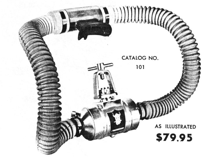
The Viking was manufactured in two main variants: the “full optional” configuration, with the air flushing lever (see Fig. 27), e the configuration named “Sportsman”, without this lever (see Fig. 28). As you can see by comparing Fig. 19 with Fig. 21, the price difference between the two configurations was of 20 $.
The whole production of the Viking and of the Norseman were completed with the use of rubber hoses (both yellow and black), of mouthpieces and of “aquastop” valves supplied by the U. S. Divers.
At the end of the Viking’s production phase in 1960 and despite its commercial flop due to the several issues described before (only 2500-2600 units produced versus the hundreds of thousands of Aqualung in its different configurations), the manufacturing of this model continues with the Norseman at Aerotec Industries Aircraft Division from Greenwich, Connecticut. This latter production phase realized results even worse.
 |
 |
| fig. 27 | fig. 28 |
The Norseman was initially produced in a configuration called “Professional”, which was identical to the Viking’s “full optional” one but with yellow hoses (see Fig. 29). Of this version only 250 units were manufactured.
Also for the Norseman the variant “Sportsman” was put in production (see Fig. 30) with yellow hoses and without the air flushing lever. This is the rarest variant ever made of these regulators with no more of 20 units manufactured.
 |
 |
| fig. 29 | fig. 30 |
The last Norseman’s variant put in production was the “Navy” designed for the Navy Department Bureau of Ships in 1962. This version, built in approximately 150 units, was not provided with both the air flushing lever and the air tap for the buddy’s emergency air supply (see Fig. 31). It was provided of black hoses and of two metal placards with the indications “INTAKE” and “EXHAUST” which were located close the connections of the inhaling and exhaling hoses, respectively (see Fig. 32). The aim of these placards was to prevent the regulator’s body being installed on the tank’s valve in a wrong position, rotated 180° from the correct one.
 |
 |
| fig. 31 | fig. 32 |
Unfortunately, due to the several technical issues explained before, there is no evidence this regulator was used by the U.S. Navy in real operating conditions. Some years after the supply of 1962, most of the Norseman Navy regulators were purchased in big batches by privates at very low prices during auctions of military surplus material.
For all these reasons, the “beer can” regulator was one of the numerous shining meteors passing through the sky of the underwater breathing apparatus inventions, during the fabulous ’50 years. This was a mythical period of pioneers, of great explorers and of a diving industry which, although still immature and naive, was capable to involve many enthusiasts, full of passion and inventiveness.
Nowadays the “beer can” regulators have become very rare pieces of diving gear, very searched and wanted by many collectors all around the world.