As a collector of historical SCUBA underwater equipment, I have always been fascinated by those gears that were introduced in the very first years of life of the so-called sport diving, a period that indicates the birth of SCUBA era with the introduction on the market, in 1946, of the first Cousteau-Gagnan self-contained breathing apparatus. The true mass diffusion of this new activity would materialize in the following decades when this equipment would be widely distributed in various parts of the world and therefore available to thousands of enthusiasts. These models, in addition to being normally rare, especially due to the very small number of units produced, contain a world of original technical solutions, often imaginative, almost always not very consistent and effective, but certainly fascinating for a technique and technology enthusiast like me. Among the solutions proposed in the very first years of the birth of SCUBA diving, one of those for which I had never managed to find sufficient information and photographic documentation, is the "Tadpole" self-contained compressed air breathing apparatus, produced by the UK company Siebe Gorman from 1948 to 1960. Of this unit, whose name “Tadpole” had been coined not by the manufacturing company but rather by the users of this device referring to the short and squat tanks that resembled the shape of the body of a tadpole, I had no great evidence with the exception of the article published by Bob Campbell in issue 39 (summer 2006) of the Historical Diving Times magazine, published by HDS - UK. The same name would also be used to identify other SCUBA units employing the same tanks, tanks that were used in the air-oxygen breathing systems installed on various military aircraft of the Second World War. After the end of the war there was great availability of this material in military warehouses at very low costs. Moreover, the production of tanks with optimal capacity, shape and characteristics for SCUBA diving had not yet started in those years and therefore these units, which had a capacity of approximately 6 litres and could be pressurized to a maximum of 125 bar, represented an obvious choice for those who wanted to build the first air breathing apparatus. As can be seen from the information provided in the Siebe Gorman catalogues, this device was proposed as a solution for professional shallow diving, as an alternative to classic hard hat diving equipment. In the images taken from one of these catalogues (see Figure 1 and Figure 2) you will in fact notice that the "Tadpole" was combined with the typical commercial diving equipment (weighted shoes and heavy wetsuit) which required the diver to walk on the bottom instead of swimming with fins on your feet. Even the mask shown in the catalogues was exclusively the "full-face" type normally used in commercial diving and initially similar to that used by the operators of the English "Chariots" (practically a copy of the Italian Manned Torpedoes or SLC) during the missions of sabotage of enemy harbours during the final phase of the Second World War. In fact, the UK company, like many other commercial firms linked to the world of professional diving, had not yet understood the great market potential that could be achieved by offering this equipment to the general public. This opportunity and the subsequent change of direction in the commercial strategies for the marketing of these products, first understood and implemented by Cousteau, would also affect Siebe Gorman, but only several years later. Having never seen during my numerous web navigations any evidence of "Tadpole" devices present in private collections or in auctions of historical underwater material, when I noticed the offer for sale of a sample of this device by a French collector, I immediately tried to get it and, fortunately, I succeeded.
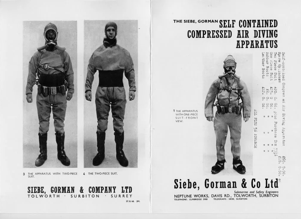 |
| Figure 1 |
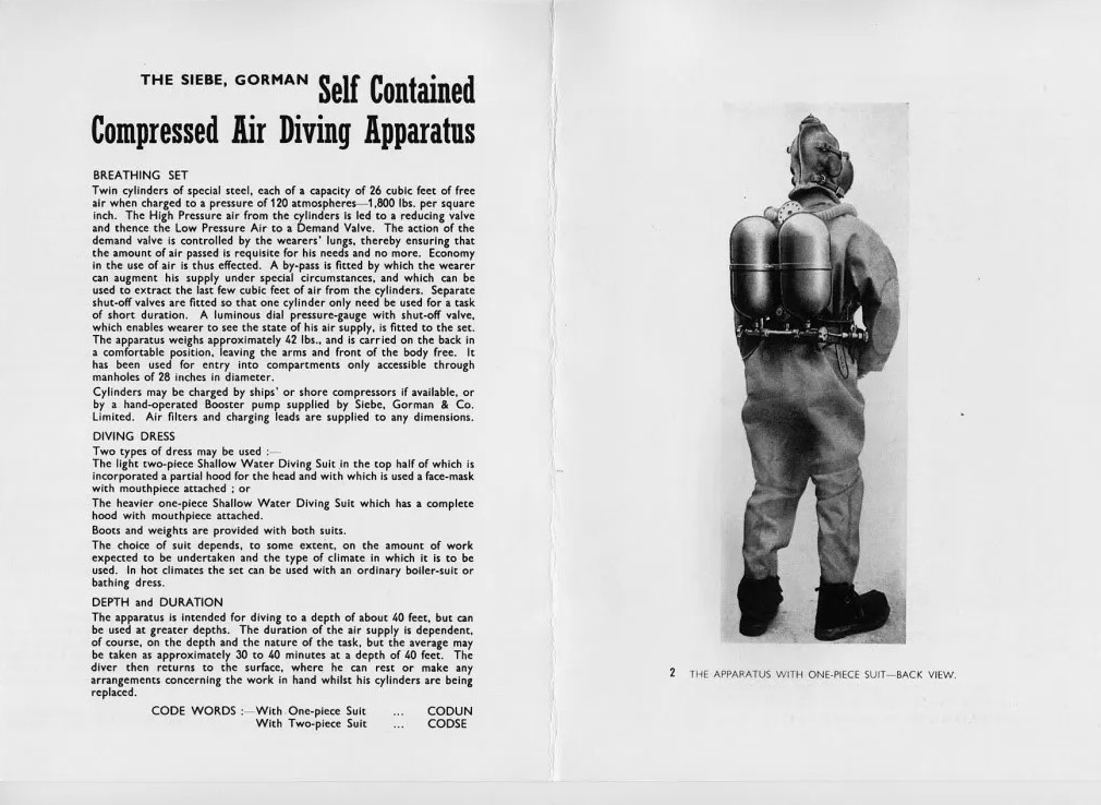 |
| Figure 2 |
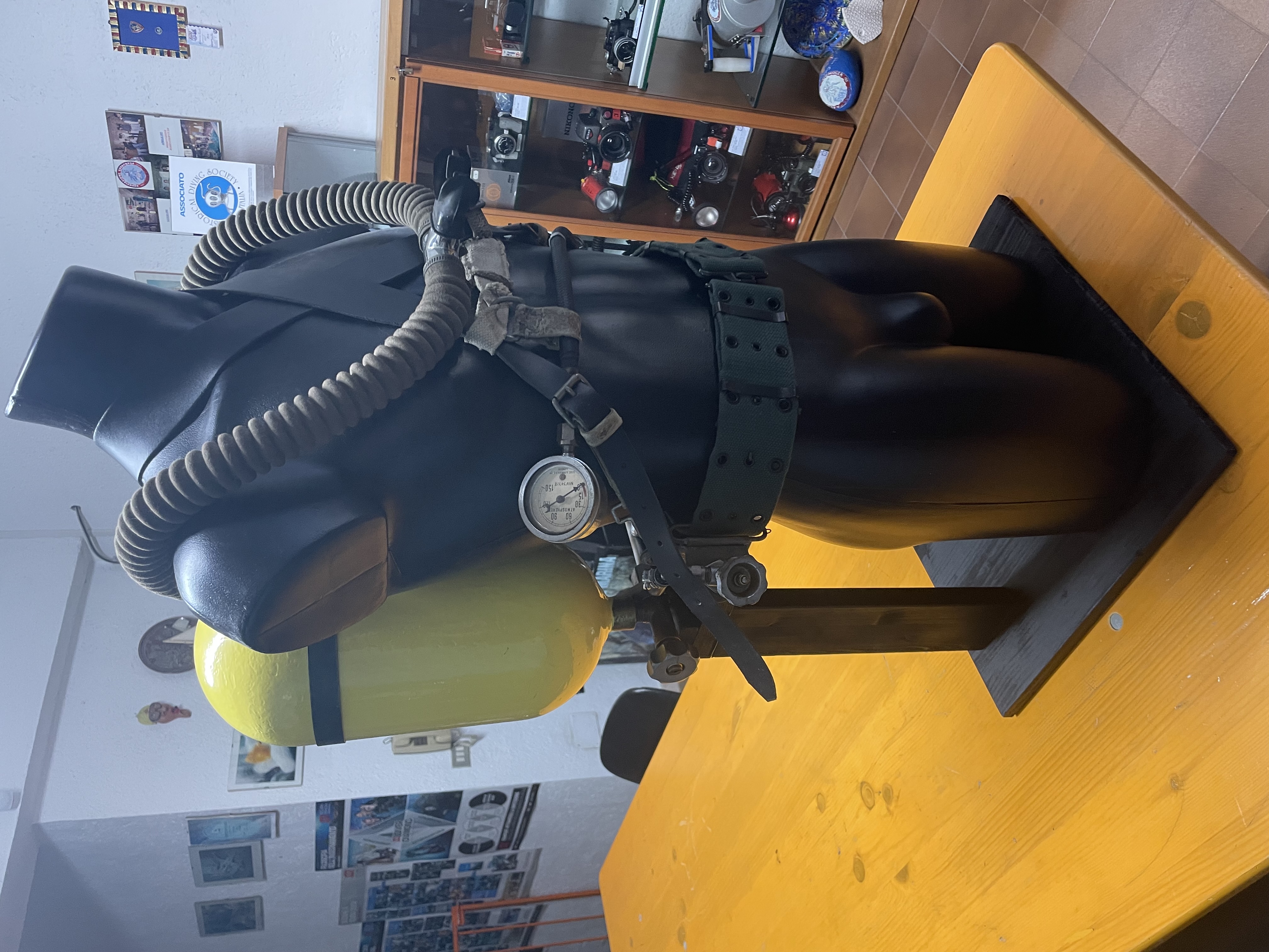
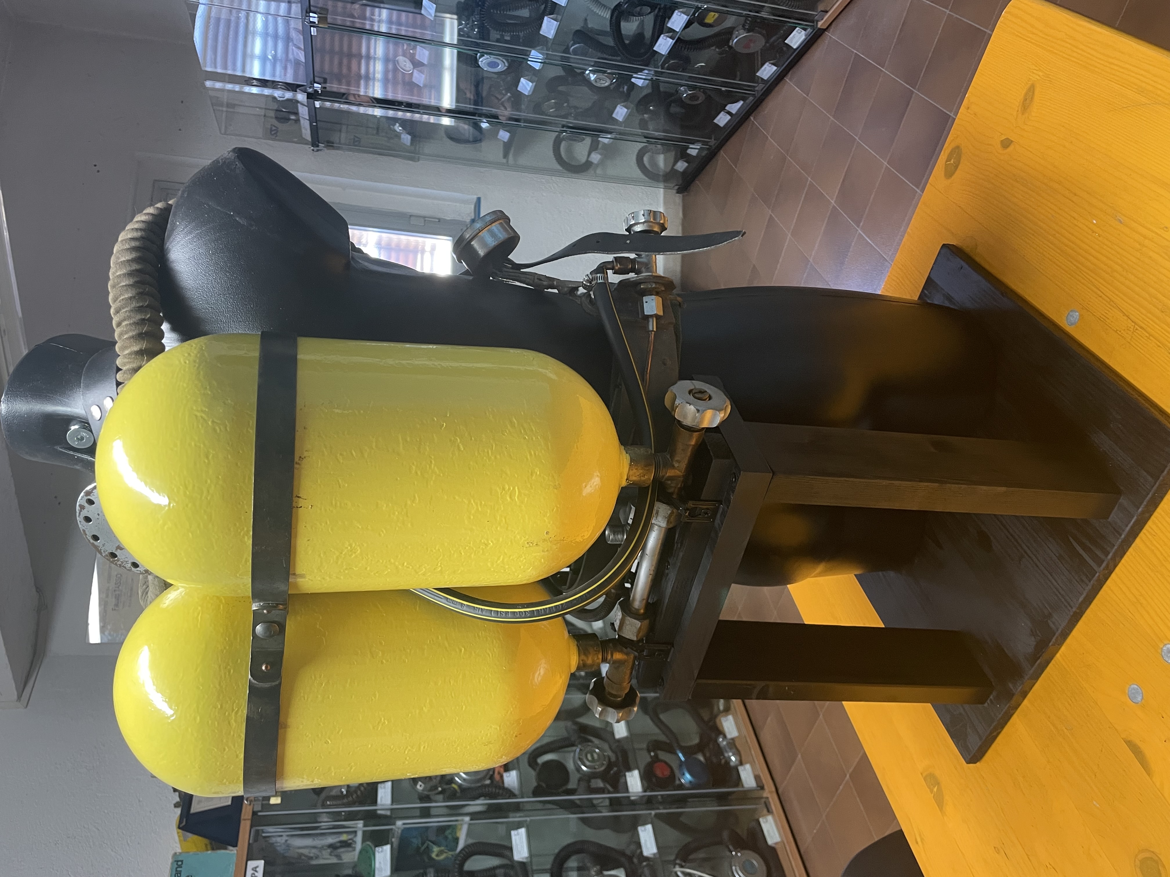
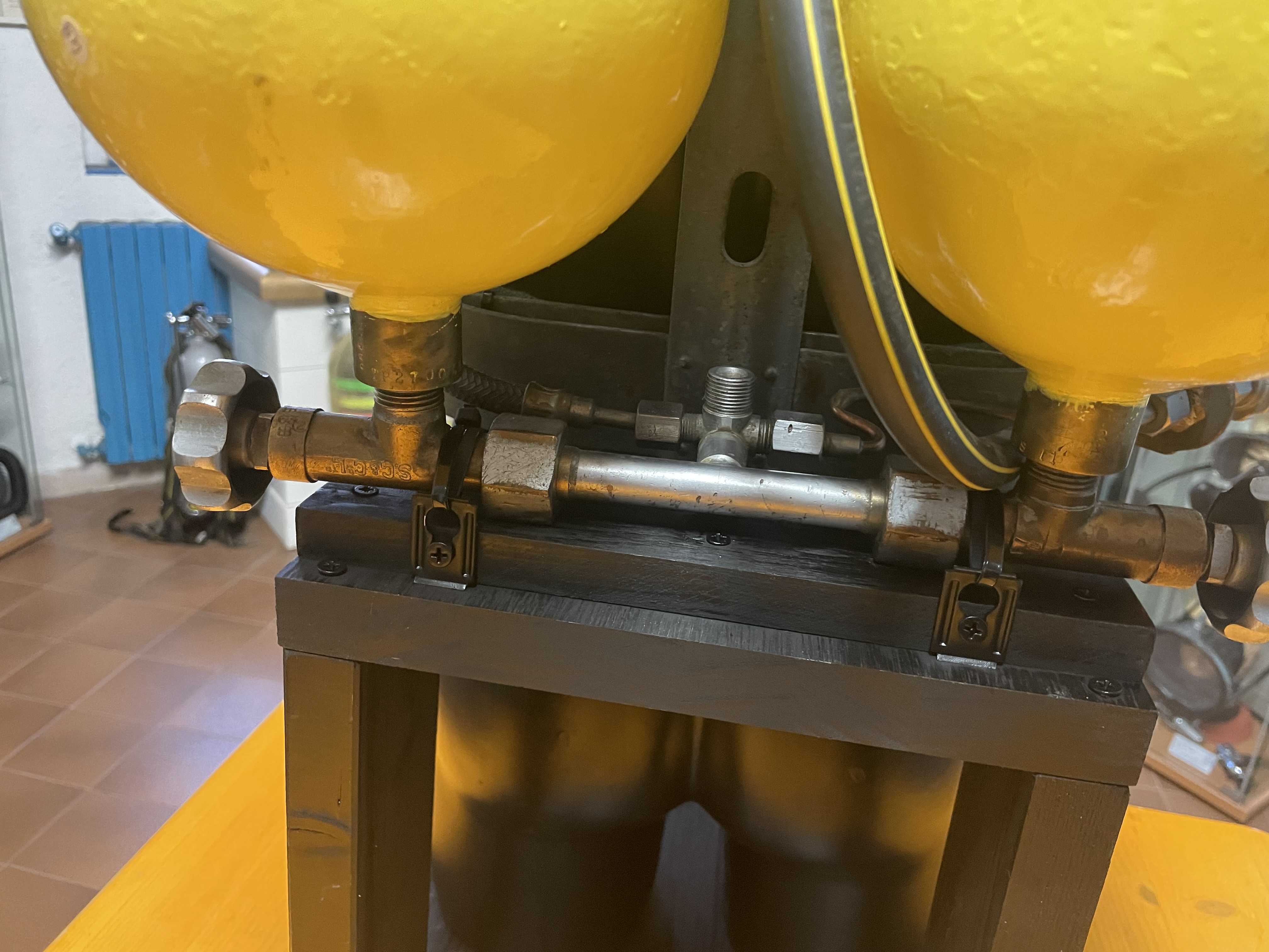
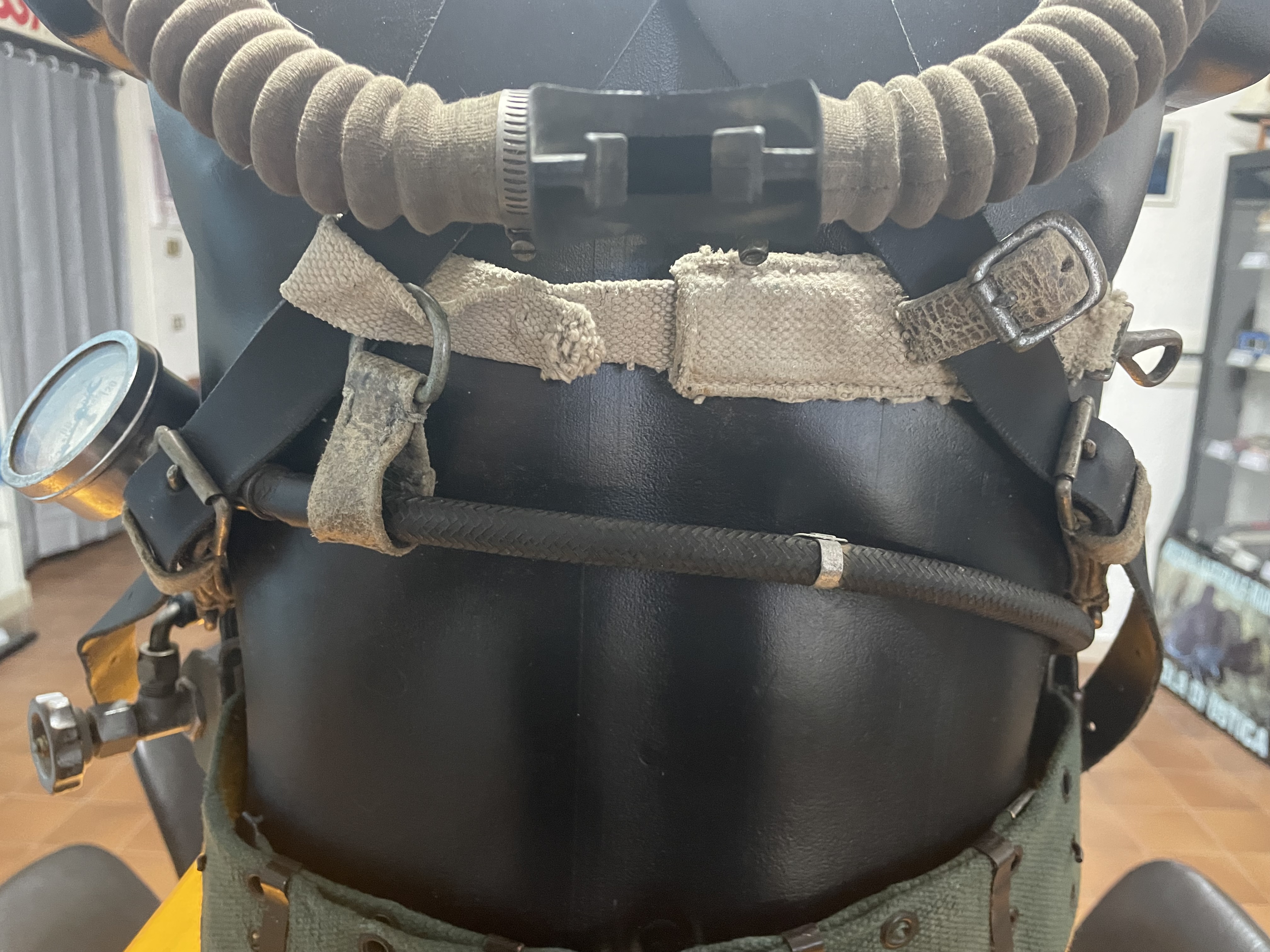
Unfortunately, the sample in question did not have the pressure reducing first stage, the ventral harness and the original mouthpiece (both for the metal and rubber parts). The upper harness part (shoulder straps) had been professionally rebuilt using leather strips and related hardware (see Figures 3, 4, 5 and 6). However, I needed more precise information on the details of this SCUBA set in order to decide an effective and reasonable rebuilding solution.
 |
 |
| Figure 3 |
Figure 4 |
 |
 |
| Figure 5 |
Figure 6 |
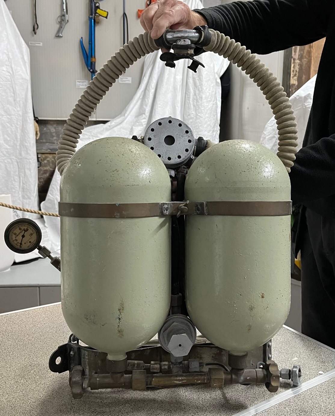
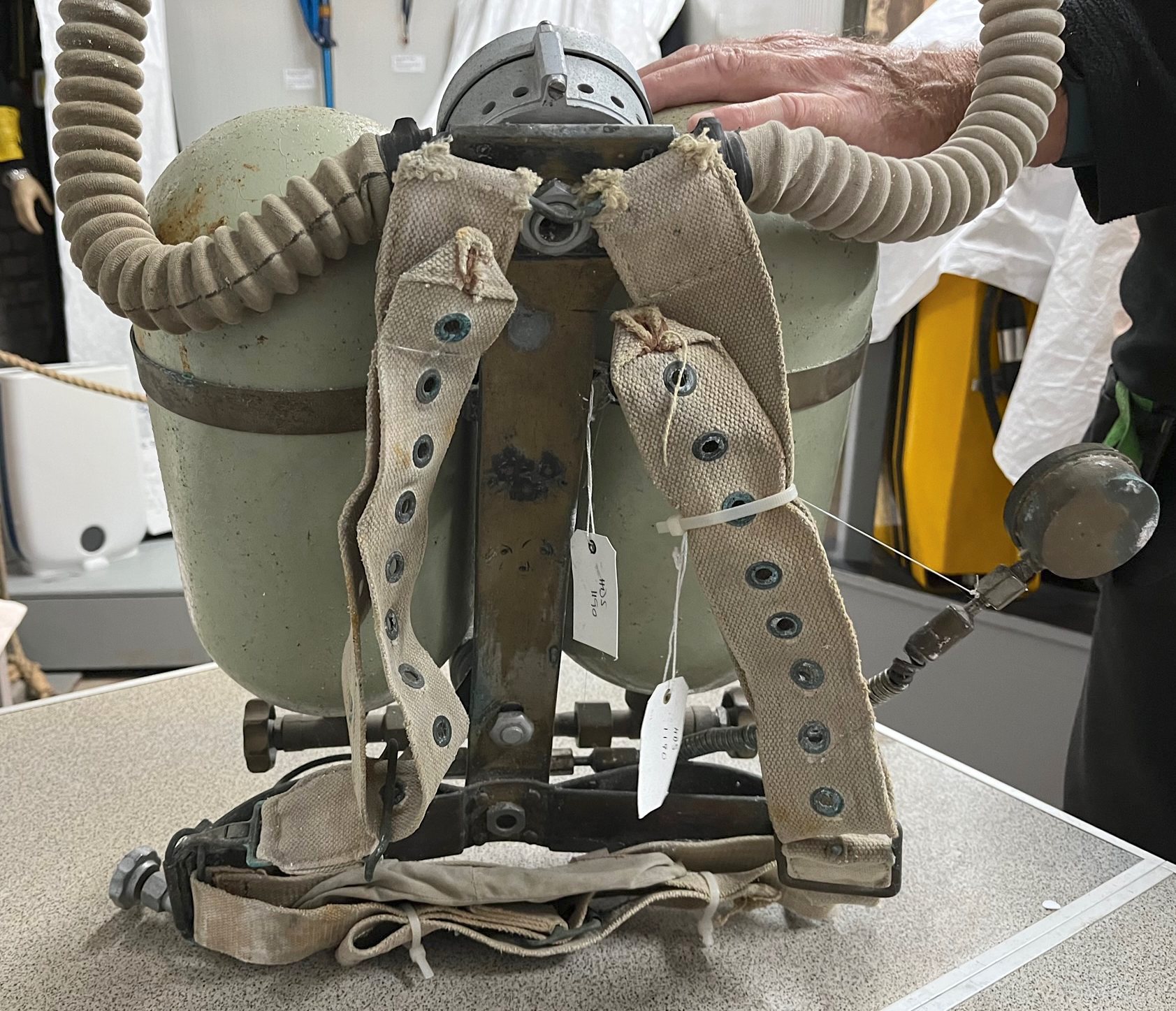
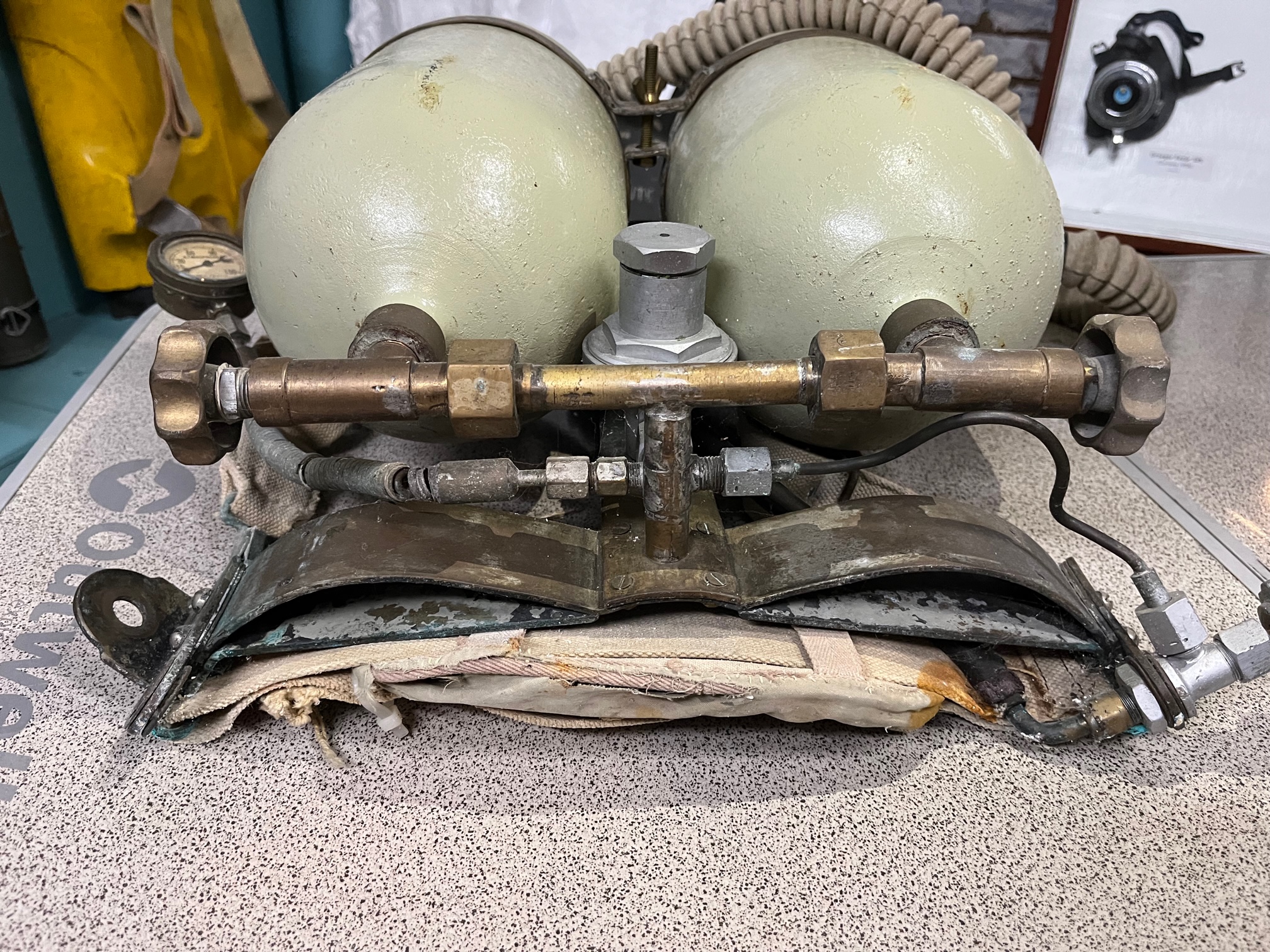
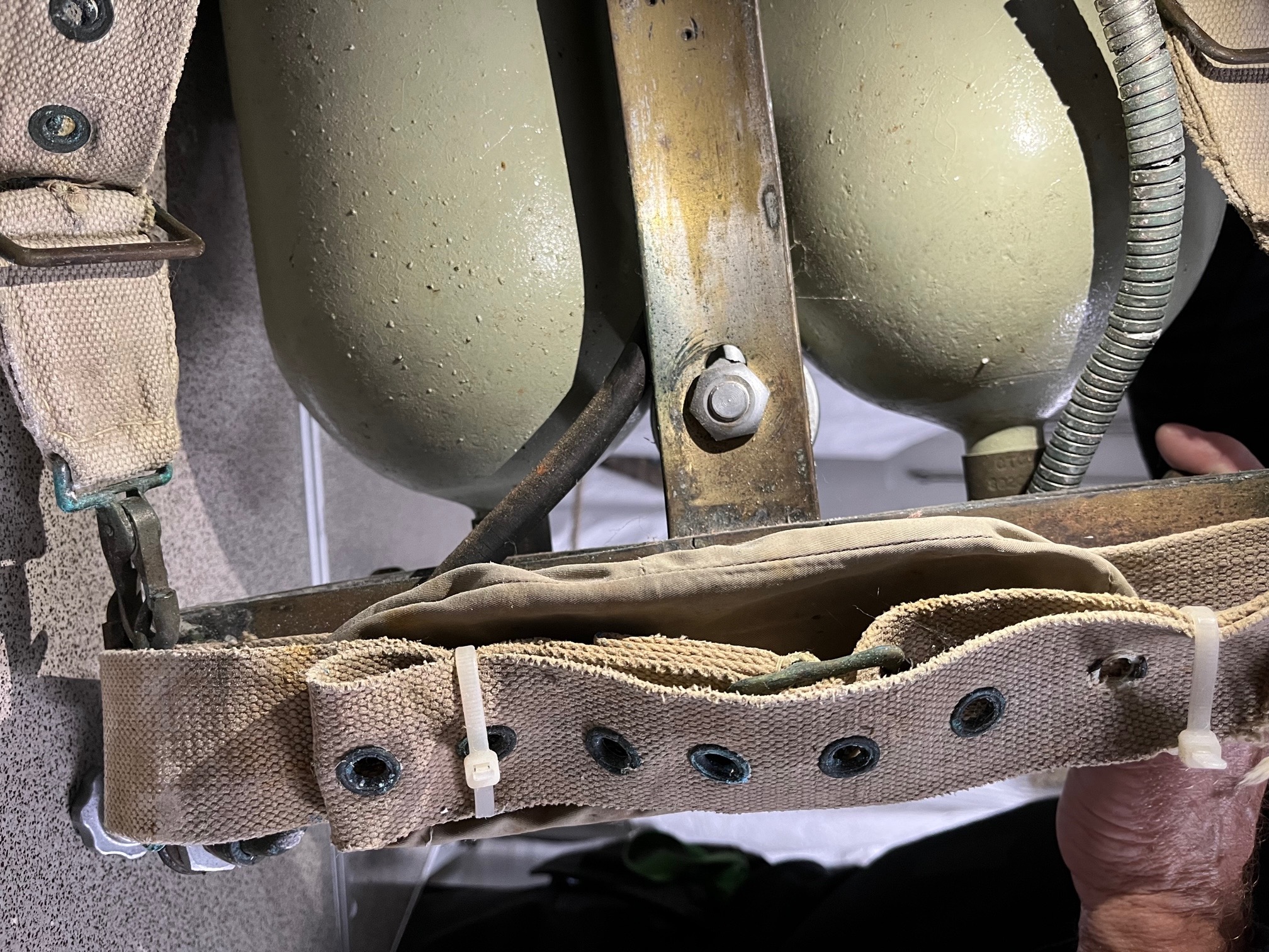
The French collector from whom I had purchased the "Tadpole" had suggested to get in touch with some members of the HDS - UK who might have information on any existing units from which I could draw the information I needed. This attempt immediately proved fruitful to a point that I was really surprised by the collaboration obtained from the HDS – UK staff who immediately put the curator of their museum of historical diving equipment at my disposal. In particular, I was provided with extensive photographic documentation of the "Tadpole" unit available in the HDS - UK museum (see Figures 7, 8, 9 and 10). From this documentation I was able to obtain the precious information necessary for the subsequent restoration and reconstruction of my sample. The editor of their magazine even offered to publish for free in the spring 2023 edition of the Historical Diving Times magazine an advertisement for the search for a first stage of the "Tadpole" which I could then purchase to replenish the missing one on my unit.
 |
 |
| Figure 7 |
Figure 8 |
 |
 |
| Figure 9 |
Figure 10 |
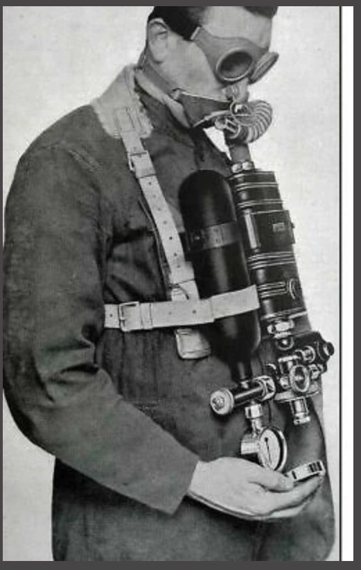
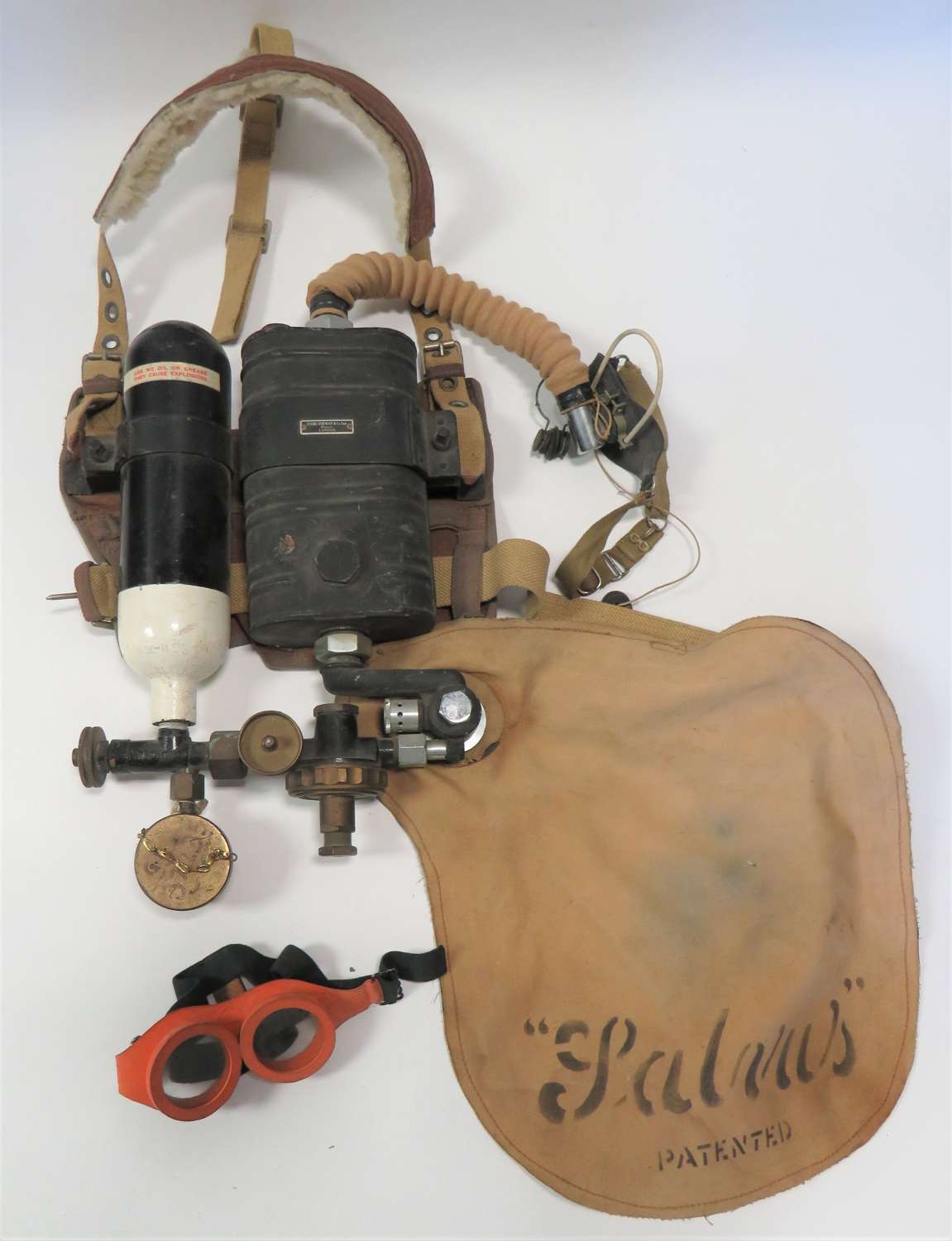
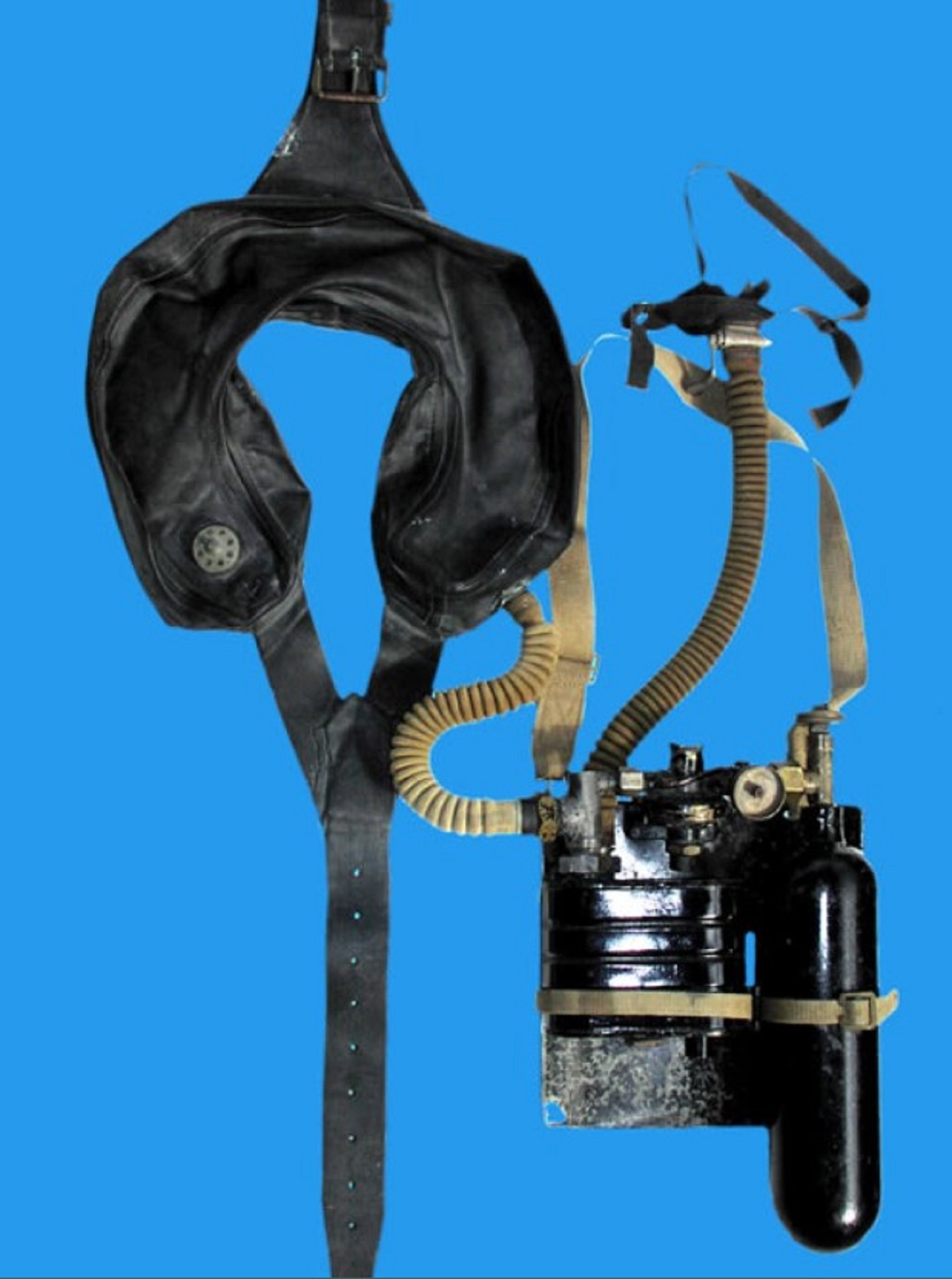
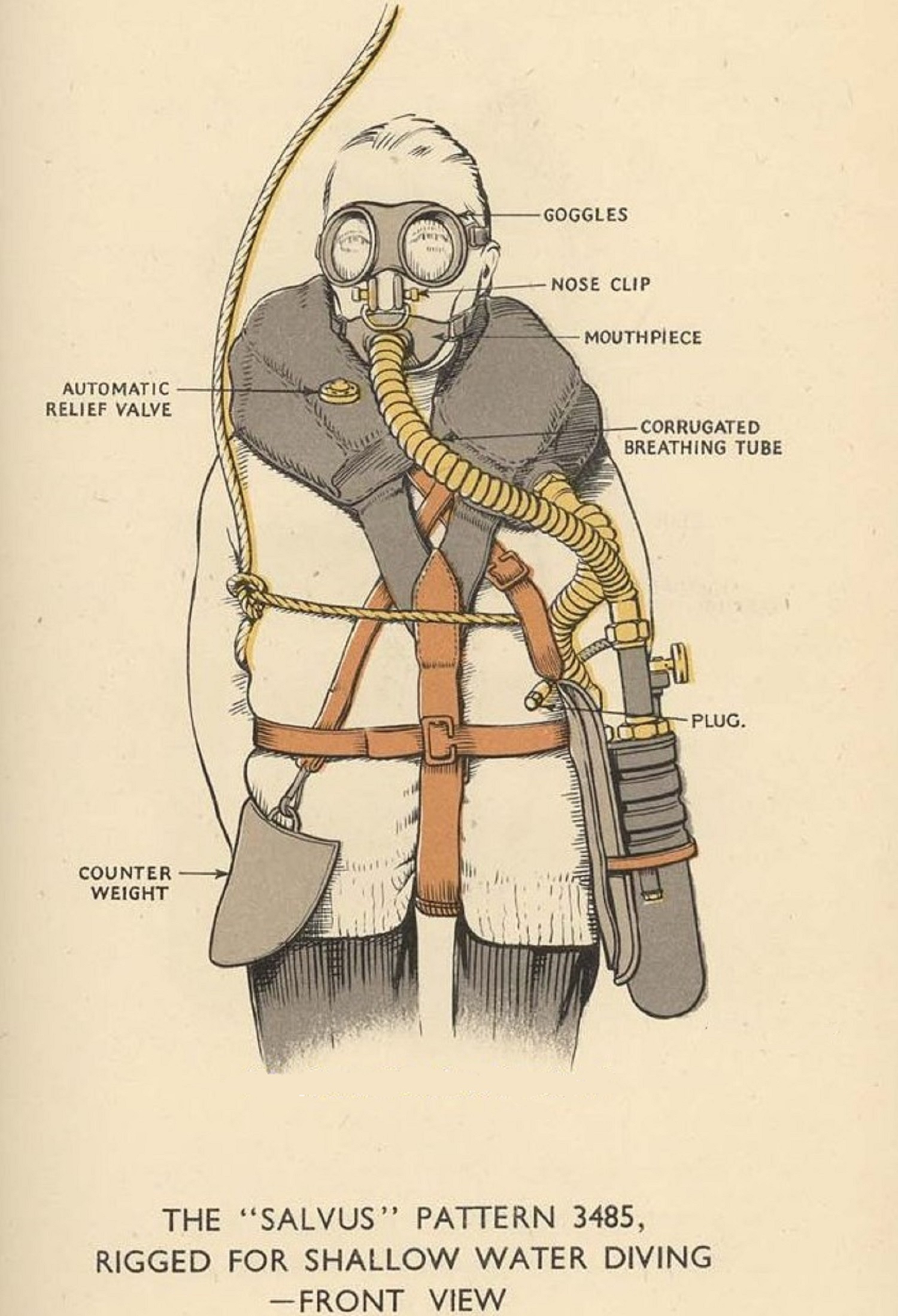
Unfortunately, the announcement in the HSD – UK magazine has not produced any response so far and therefore I started thinking about how I could rebuild the missing first stage. However, not having any manufacturing drawing of this component, I thought long and hard about the different solutions. Among these, the one that seemed most suitable to me in obtaining something very similar to the original part, not only from an aesthetic point of view but also from that of operating mechanism and internal components, is the one described below. Some time ago I purchased for my collection a sample of an oxygen rebreathing apparatus produced by Siebe Gorman from the 1920s to the end of the 1950s. This device is the "Salvus" (see Figure 11 and Figure 12) which was proposed for a number of applications, including those related to mining industry and fire-fighting squads emergency procedures, but also for breathing pure oxygen during the decompression stages inside the diving bells used in commercial underwater operations. This last type of application is described in the article by Ginge Fullen published in issue 76 of the Historical Diving Times magazine published by HDS - UK. The “Salvus” was also employed for a long time by the Royal Navy which, for underwater applications, used a slightly different version (Admiralty pattern 3485), as shown in Figure 13 and Figure 14.
 |
 |
| Figure 11 |
Figure 12 |
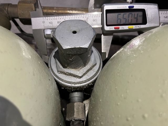
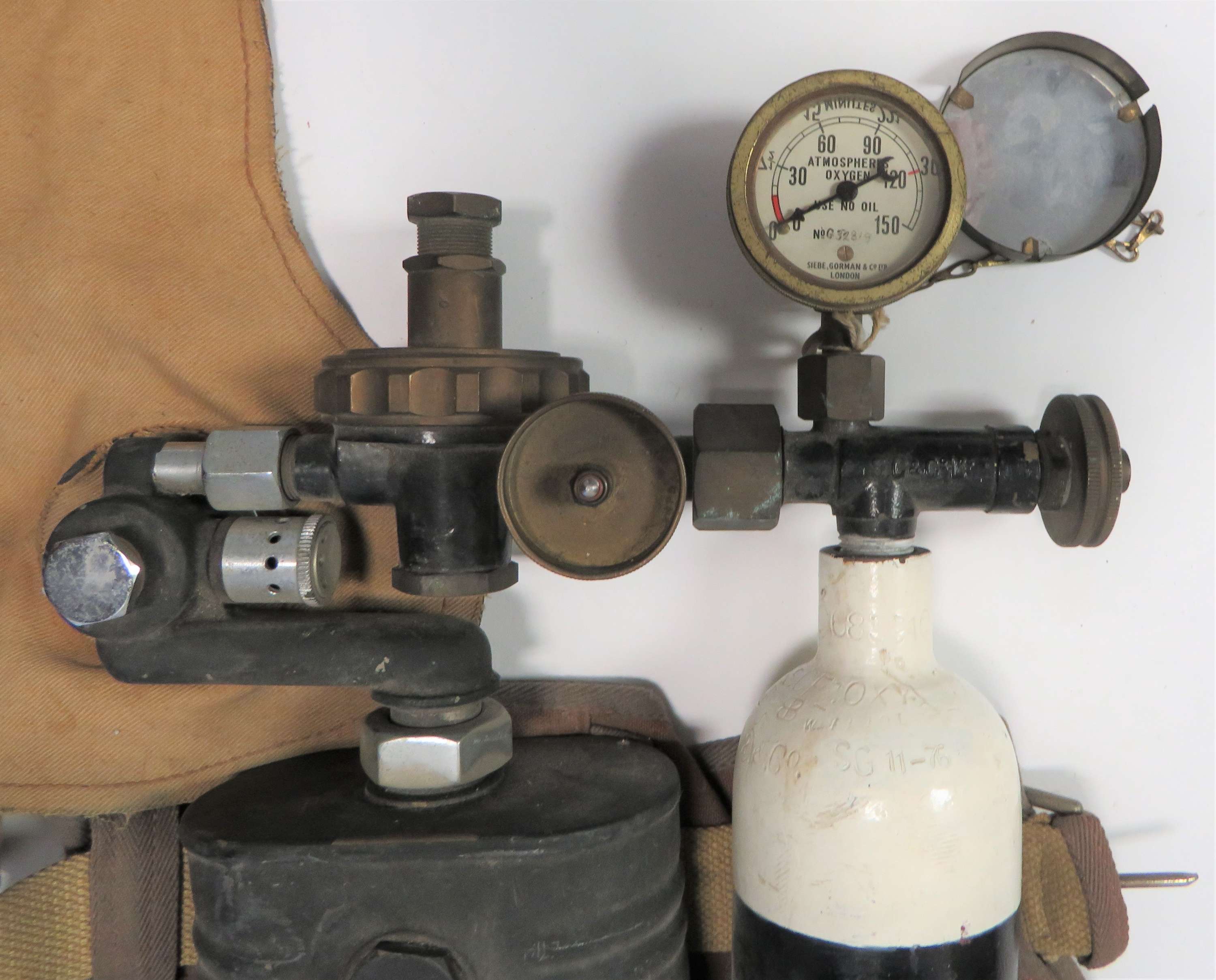
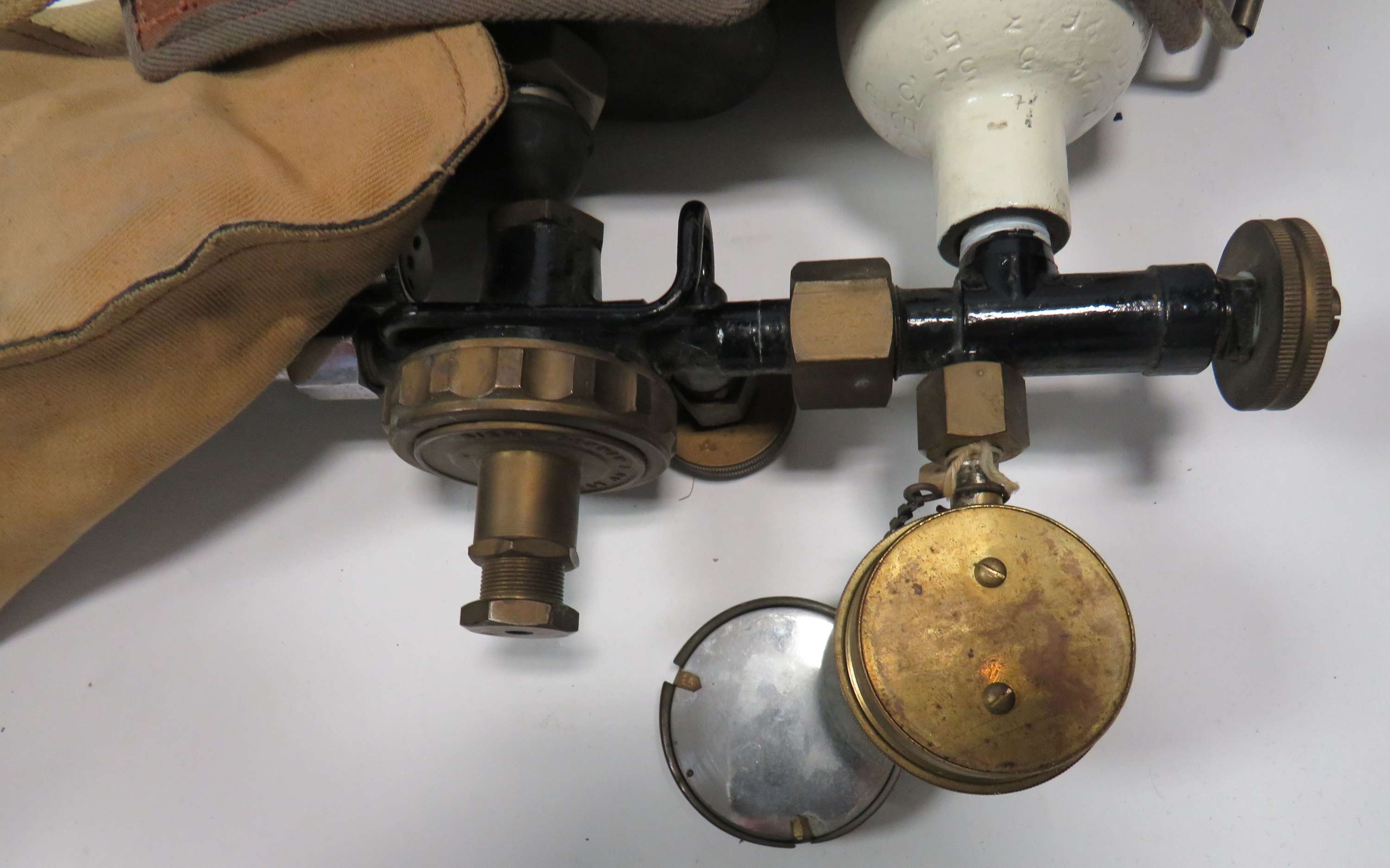
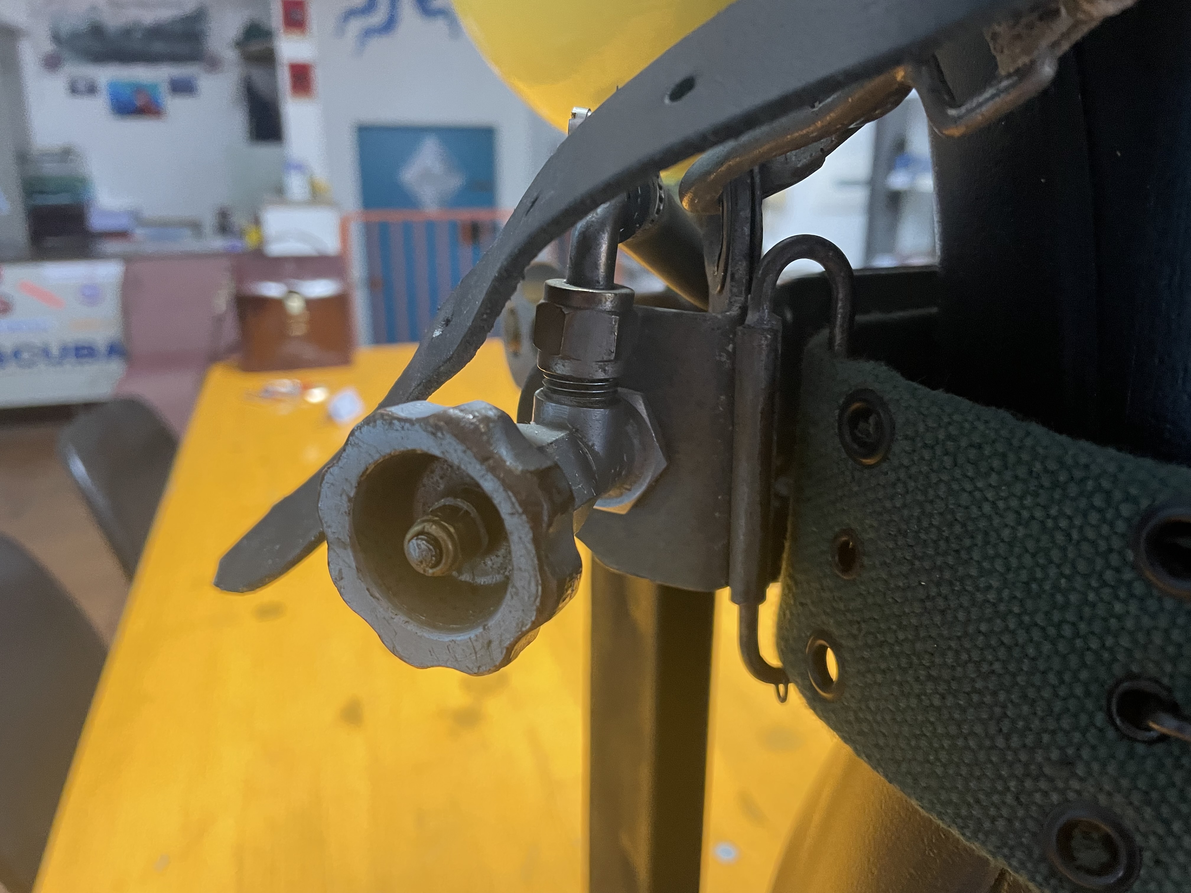
What clearly changed in the underwater version compared to the standard one was the lung bag, placed around the diver’s neck rather than on the operator's left side, and the harness which also had a crotch strap. On the contrary, the entire mechanical arrangement remained substantially the same for the two configurations. Comparing the two pressure reducers, that of the first stage of the "Tadpole" (see Figure 15) and that of the "Salvus", this latter installed between the oxygen tank and the soda lime canister (see Figure 16), I realized that these two versions were very similar both in general dimensions and in the layout of the internal components. This conclusion is also supported by logical considerations: since producing both models in the same period, Siebe Gorman should have had every interest in standardizing as much as possible the components of the products in the range for obvious reasons of economy of scale and simplification of production. The major difference between the two versions of pressure reducer consists in the by-pass mechanism, integrated in the first stage of the “Salvus” (see Figure 16 and Figure 17) and separated by a dedicated shut-off valve and external pipe in the “Tadpole” (see Figure 18).
 |
 |
| Figure 13 |
Figure 14 |
 |
 |
| Figure 15 |
Figure 16 |
 |
 |
| Figure 17 |
Figure 18 |
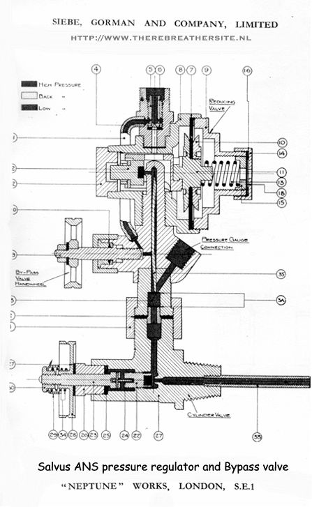
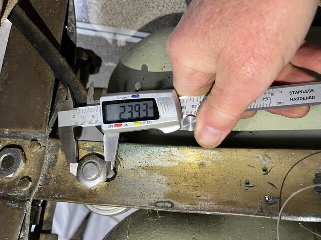
The internal operating schematic of this type of pressure reducer is shown in Figure 19. It is a classic offering diaphragm type pressure reducer with adjustable outlet pressure, derived from those used in gas welding systems. In the schematic you can also appreciate the layout of the by-pass system located between the oxygen tank outlet and the connection downstream of the reducer. This by-pass solution was often used on these devices for various reasons (to provide an additional gas flow in cases where the flow rate through the reducer proved insufficient, to ensure an alternative gas supply system in case of blockage of the reducer, to allow the use of all the gas contained in the tanks, etc.). In underwater applications the by-pass was also often used to eliminate water that had penetrated inside the breathing hoses, in cases where the mouthpiece was voluntarily or accidentally removed from the mouth. Therefore, in order to convert the "Salvus" reducer into a version compatible with the "Tadpole", I would have had to remove the by-pass mechanism integrated in the lower body of the reducer and rebuild the pipe section upstream of the reducer. In addition, a stud integrated with the high-pressure compartment plug should have realized. This stud was designed to secure the reducer to the supporting frame of the "Tadpole" with the related nut (see Figure 20).
 |
 |
| Figure 19 |
Figure 20 |
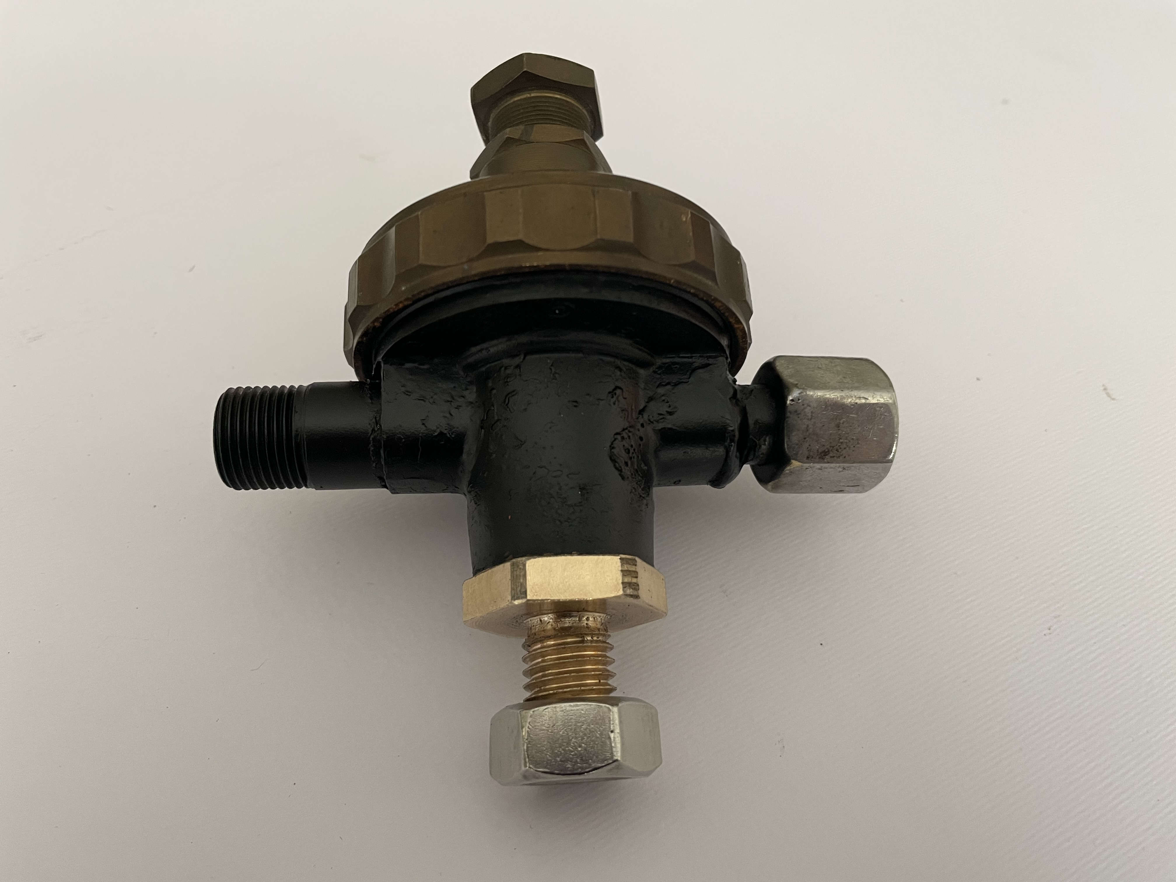
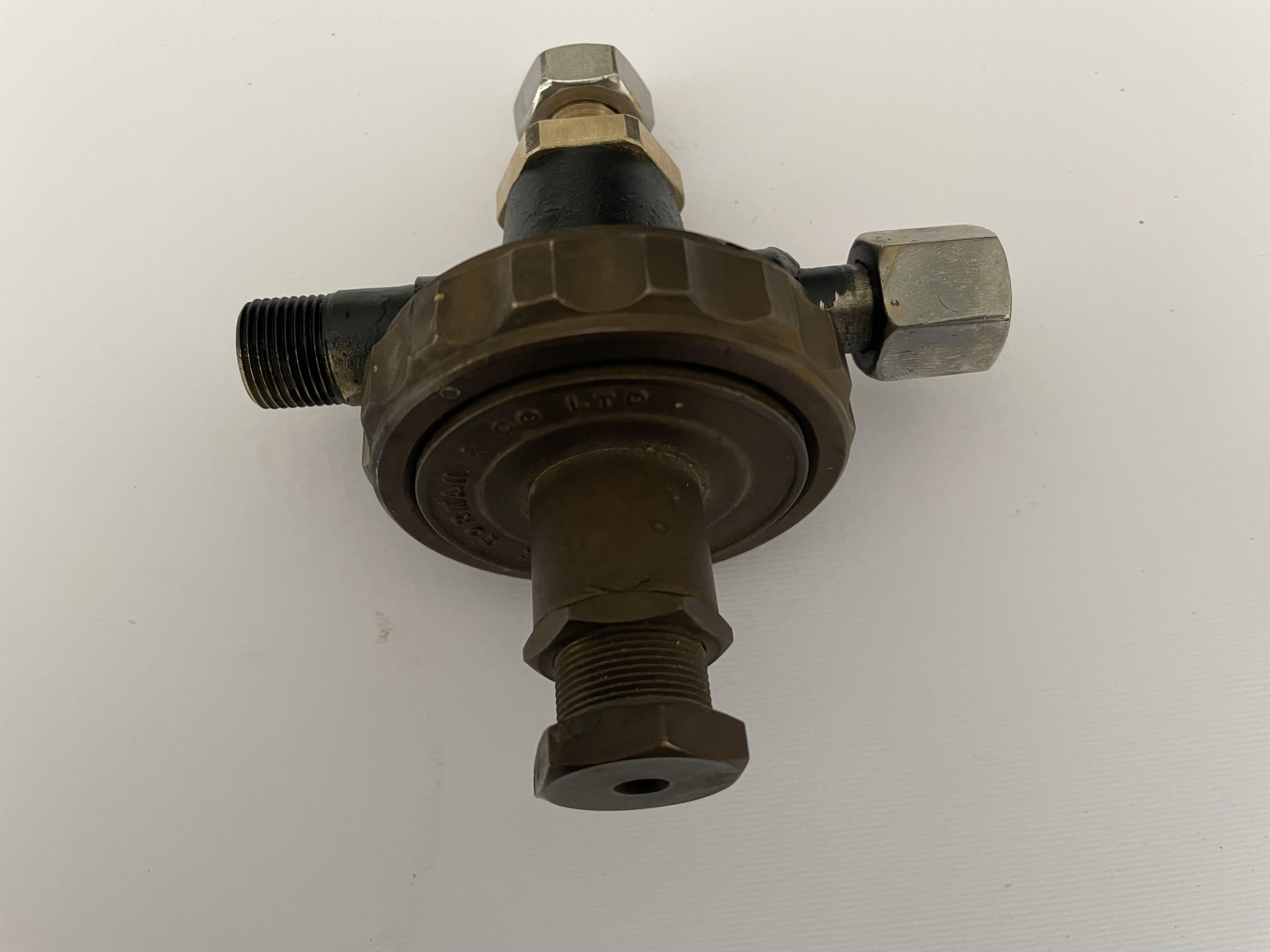
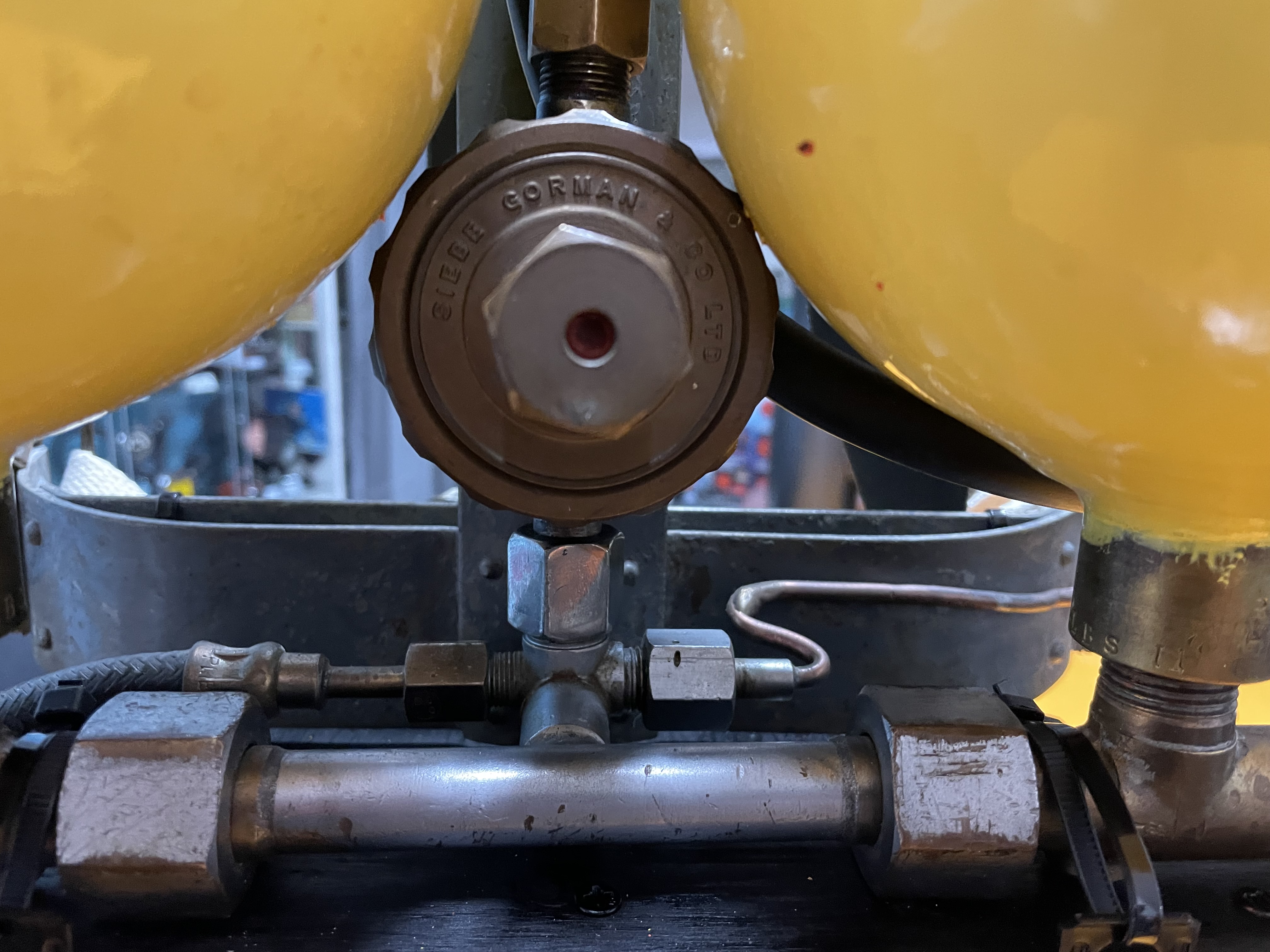
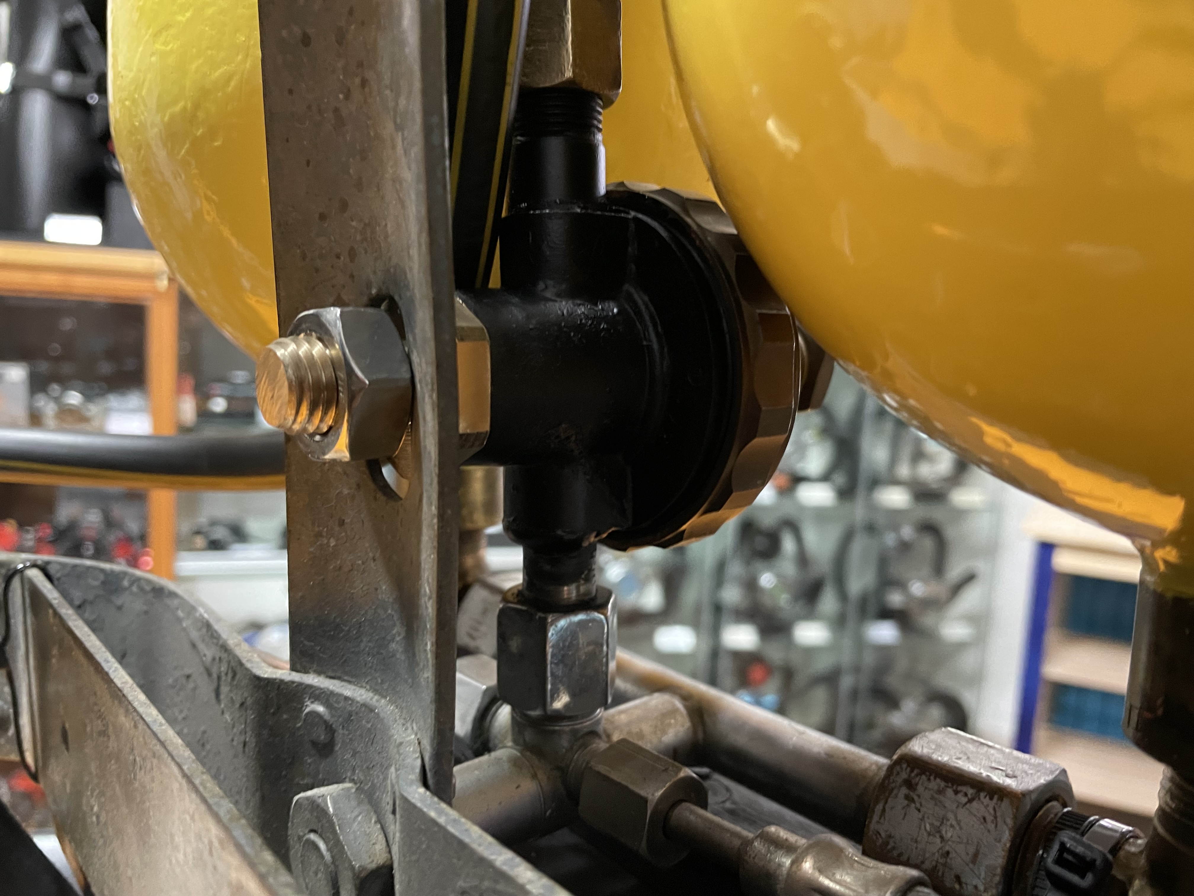
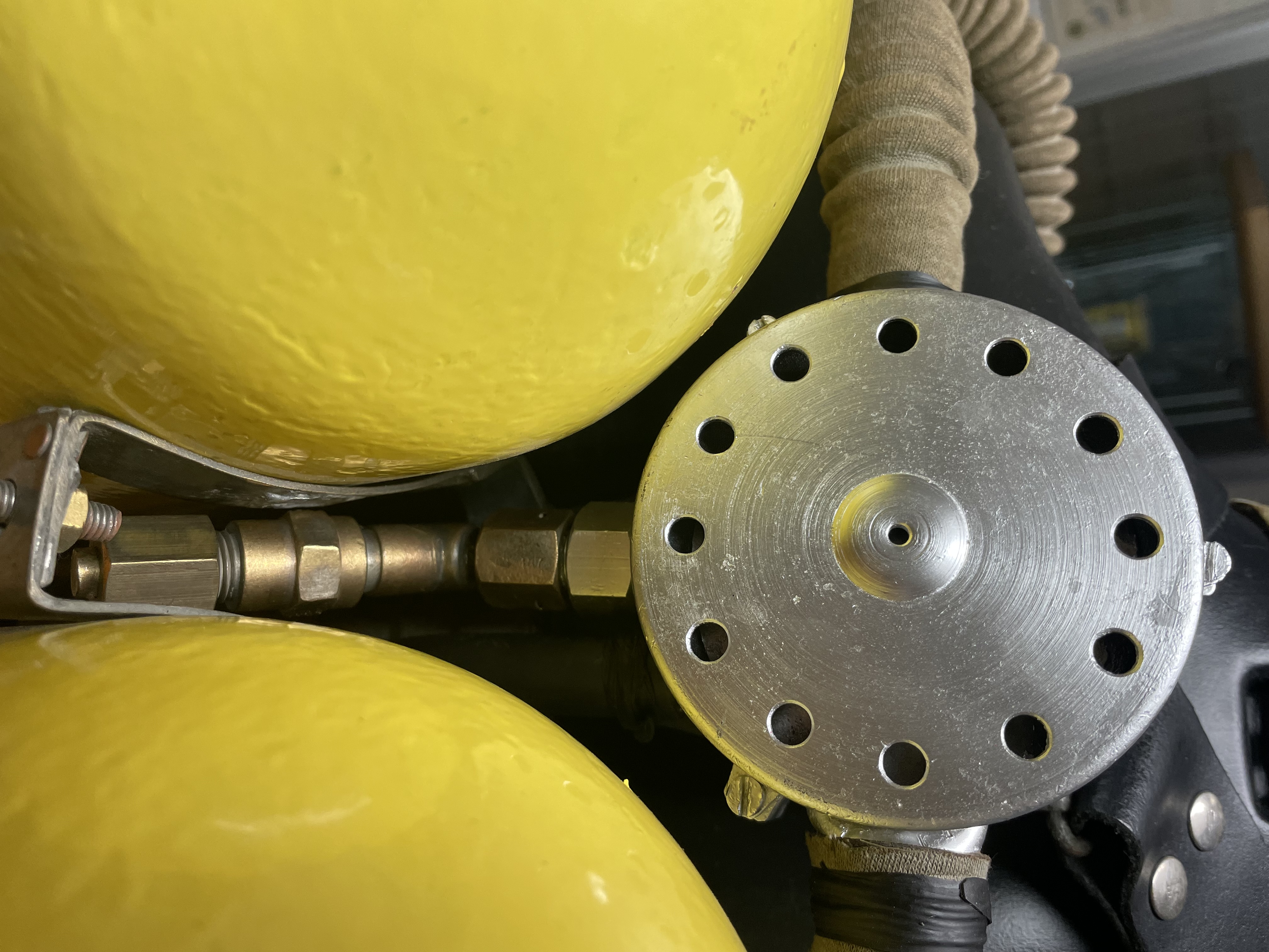
This task was completed with the help of a company specialized in mechanical machining which, after removing the by-pass mechanism of the first stage of the "Salvus", applied the high-pressure pipe and adapter compatible with the “Tadpole” tanks valve fitting and completely rebuilt the high-pressure compartment plug with the integral stud (see Figure 21 and Figure 22). The first stage, thus modified, was then installed on the “Tadpole” tanks valve, as shown in Figure 23 and Figure 24.
After having unsuccessful searched for an original replacement of the mouthpiece assembly (as can be seen from the photos of the "Tadpole" unit preserved in the HDS - UK museum this was made of curved metal tube) I decided to personally try to rebuild this component to be as much as possible similar to the original one. To start this attempt, I searched and found a brass tube on eBay with an external diameter of 25 mm (about 1 inch) and a thickness of 1 mm. In fact, I knew well that the dimensions of these tubes at that time were normally expressed in inches and, measuring other metal mouthpieces belonging to different examples of double hose regulators, these all had an external diameter of 1 inch. There were also no doubts about the choice of tube material: this, like most of the metal components of those equipment, were made of brass, a material that was easy to mechanically machine and intrinsically resistant to sea water corrosion.
 |
 |
| Figure 21 |
Figure 22 |
 |
 |
| Figure 23 |
Figure 24 |
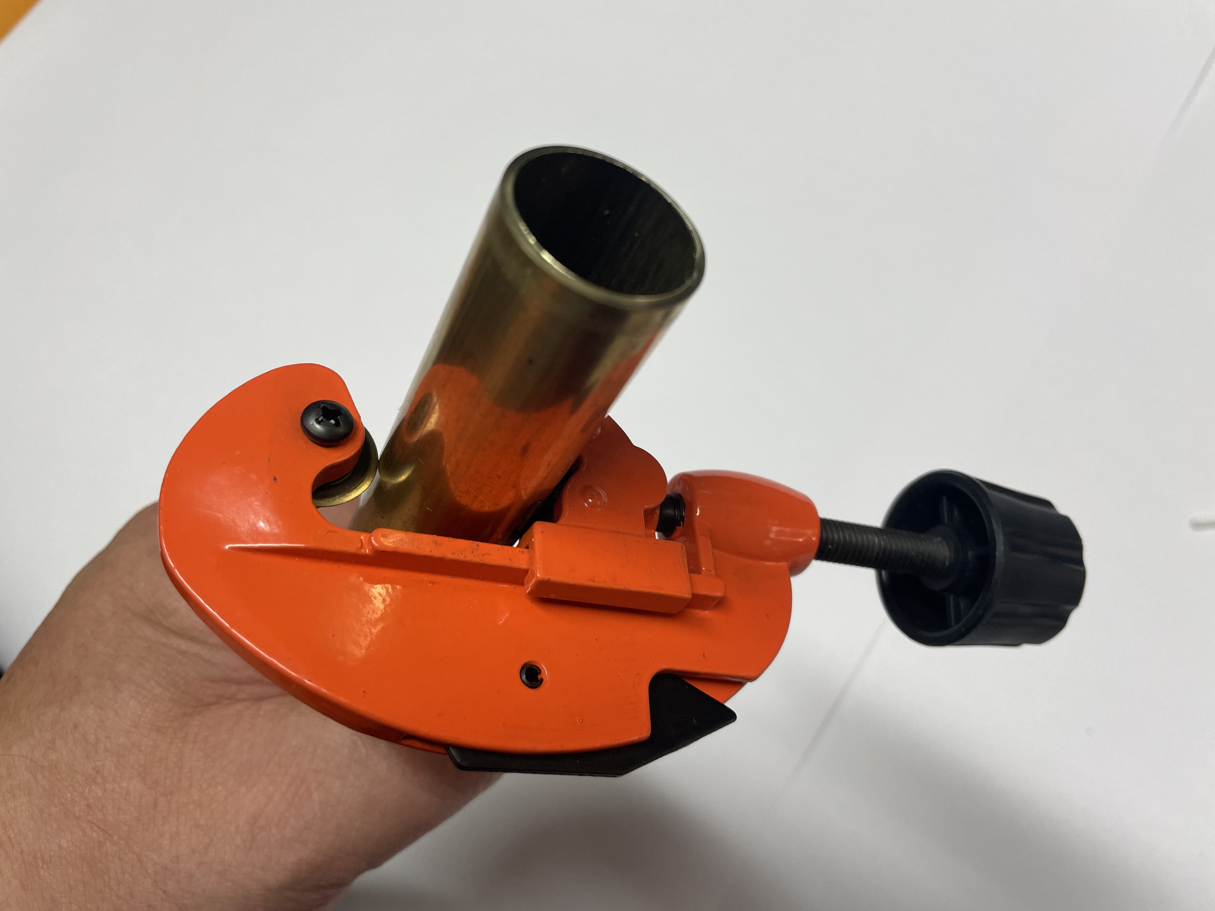
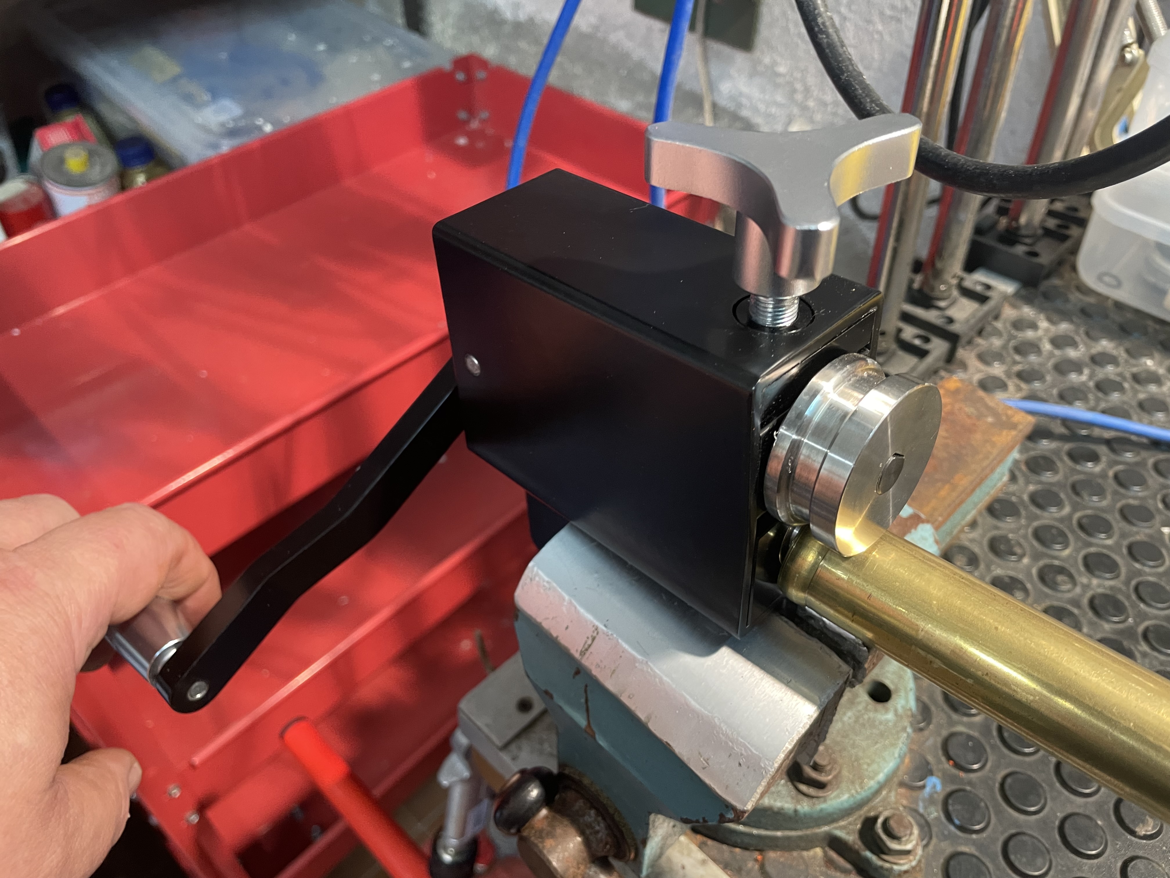
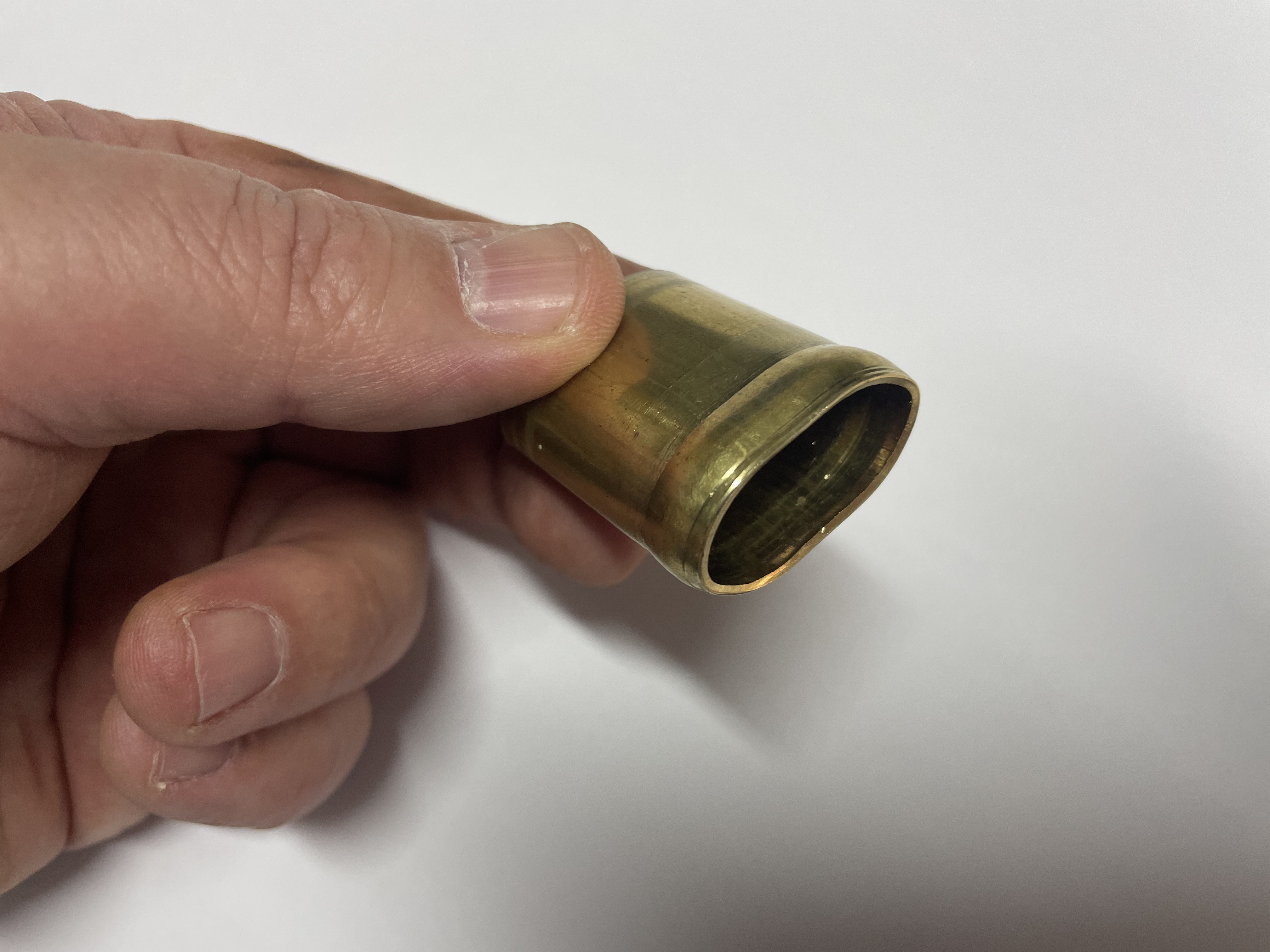
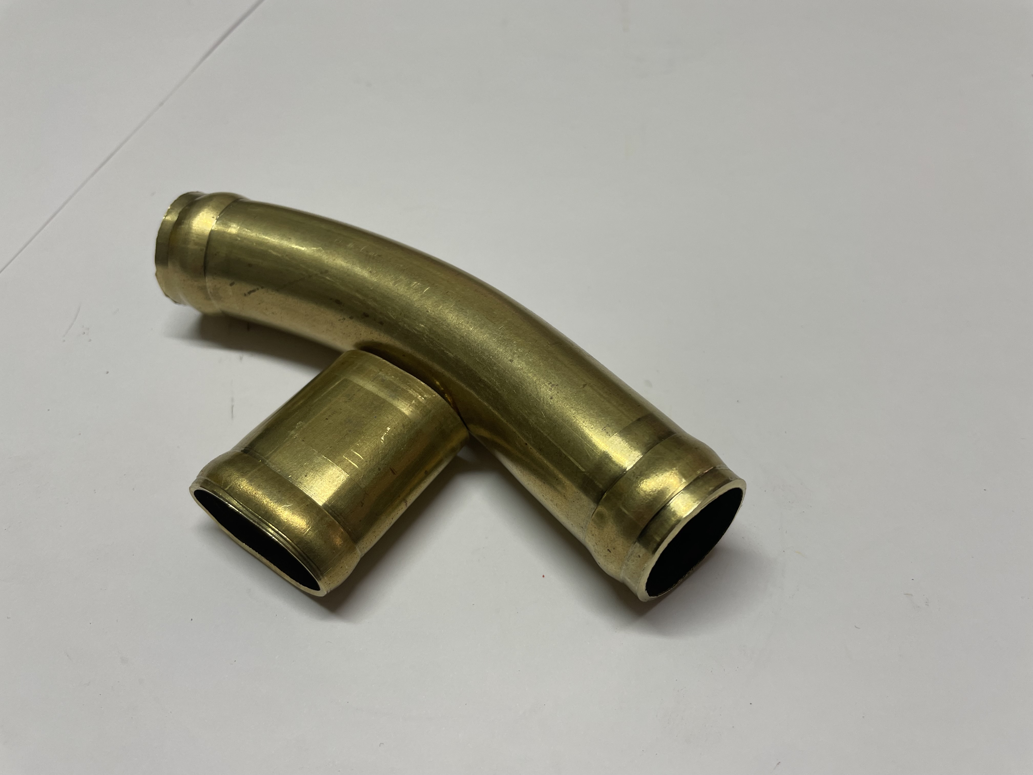
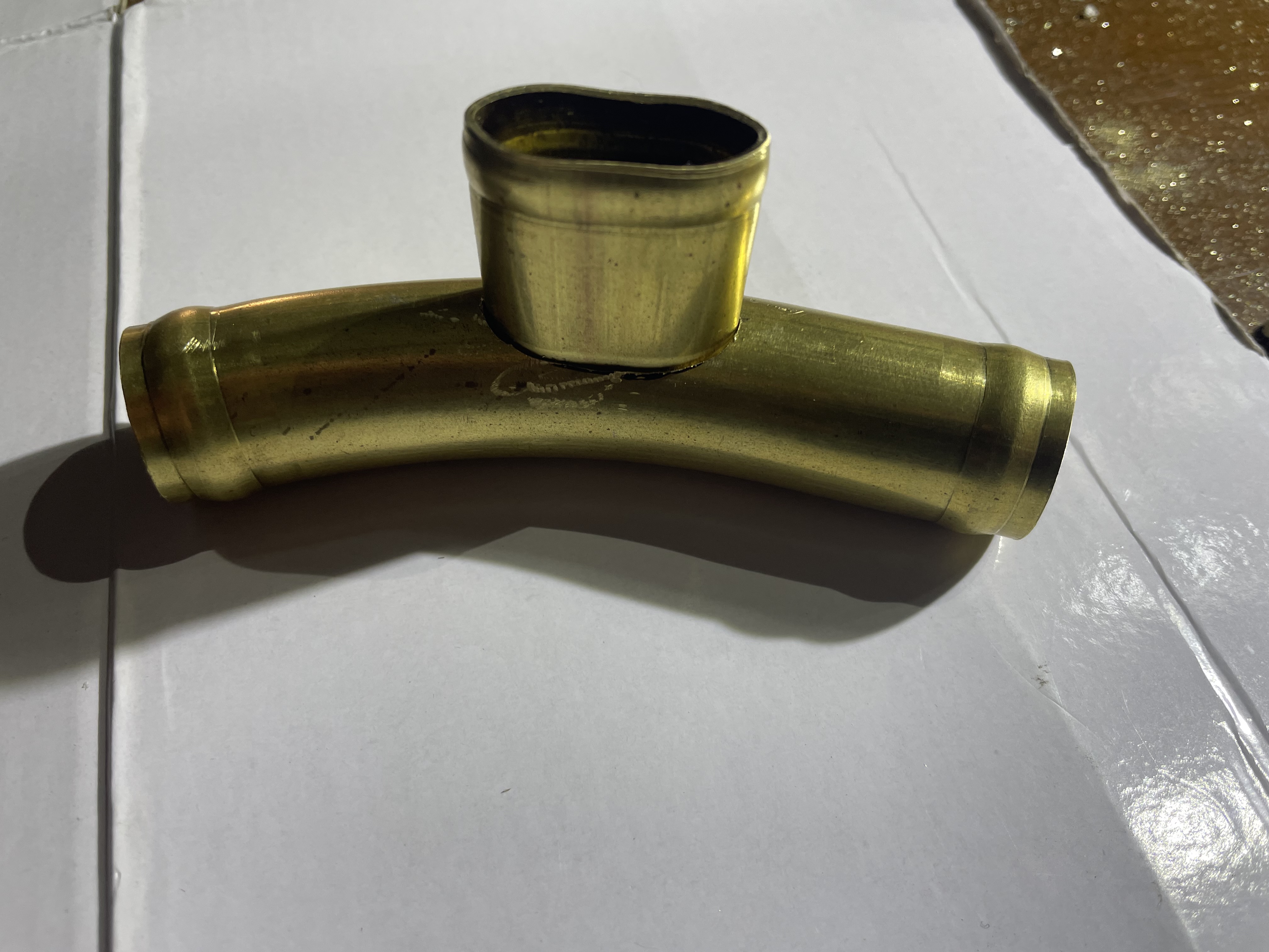
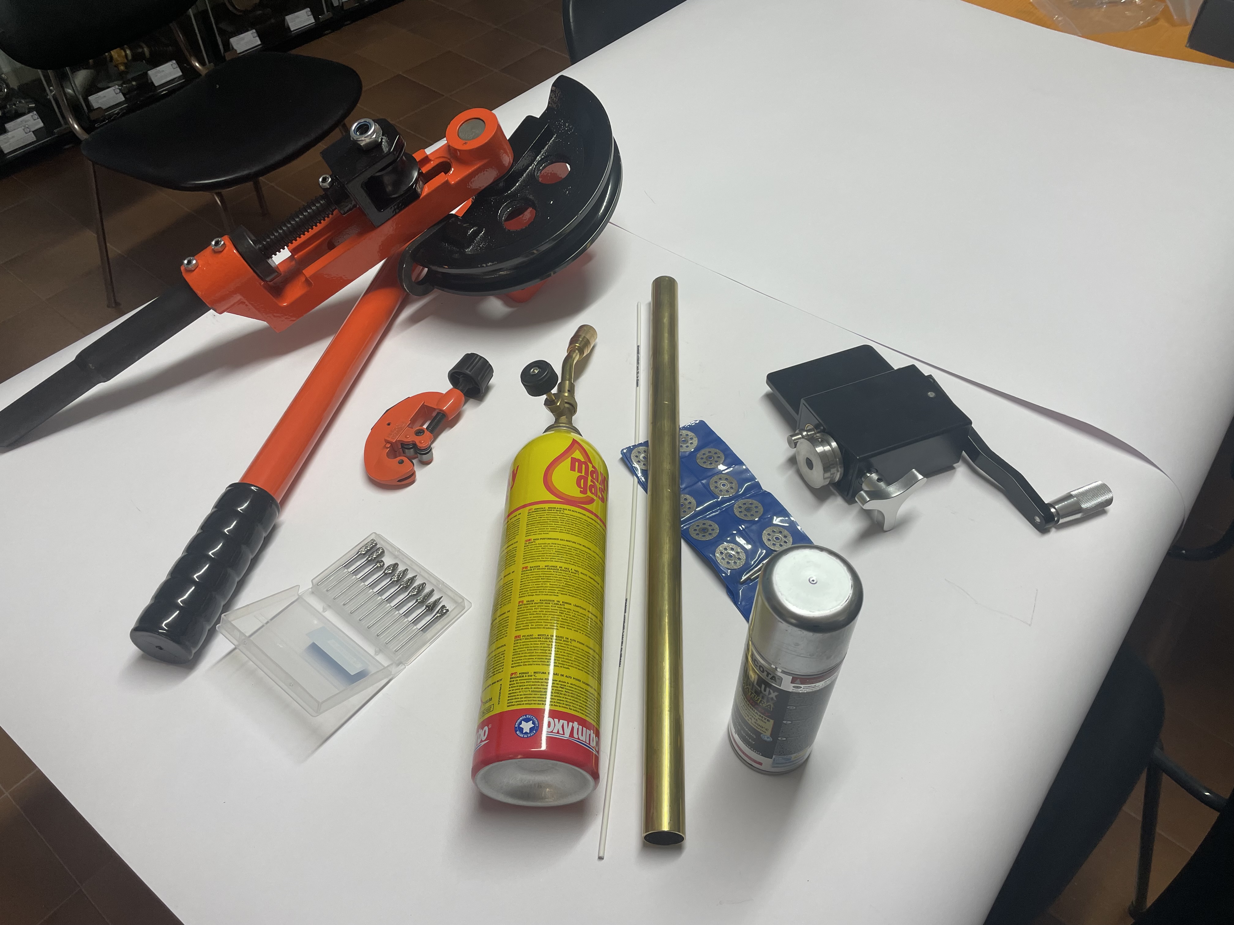
The brass tube was cut to size according to the required dimensions using a simple wheel hose cutter (see Figure 25), the same as those used by plumbers for the installation of domestic heating systems. This tool is designed to make very precise cuts on materials that are not too hard such as copper, aluminium and brass. The problem of the curvature that I had to give to the mouthpiece was solved by using a manual tubes bender, also available on eBay at affordable prices. This equipment is capable of bending tubes of different diameters and thicknesses up to a maximum diameter of 25 mm. The edging that these nozzles normally had on their end part to prevent the rubber hoses from coming off during use, even after having been tightened with appropriate clamps, could be made using a manual edging machine also available on eBay at reasonable prices (see Figure 26). This equipment is mainly used to edge the rigid pipes for car air conditioning systems but can also be effectively used for our purposes. The central part of the nozzle, where the rubber mouthpiece had to be mounted, could have been made starting from the 1 inch brass tube, adequately shaped by crushing it in a vice, and then brazed to the body of the metal nozzle. Before brazing the two parts of the nozzle, I made a housing in the curved tube by using small machining milling tools designed for multi-purpose Dremel type electrical devices (see Figure 27, Figure 28 and Figure 29). Brazing is simpler and more accessible than other forms of welding because it requires much simpler and cheaper torches and much lower working temperatures. This process, moreover, is the same used at the time to fabricate these components. The complete set of materials and equipment used for the rebuilt of the mouthpiece nozzle is shown in Figure 30.
 |
 |
| Figure 25 |
Figure 26 |
 |
 |
| Figure 27 |
Figure 28 |
 |
 |
| Figure 29 |
Figure 30 |
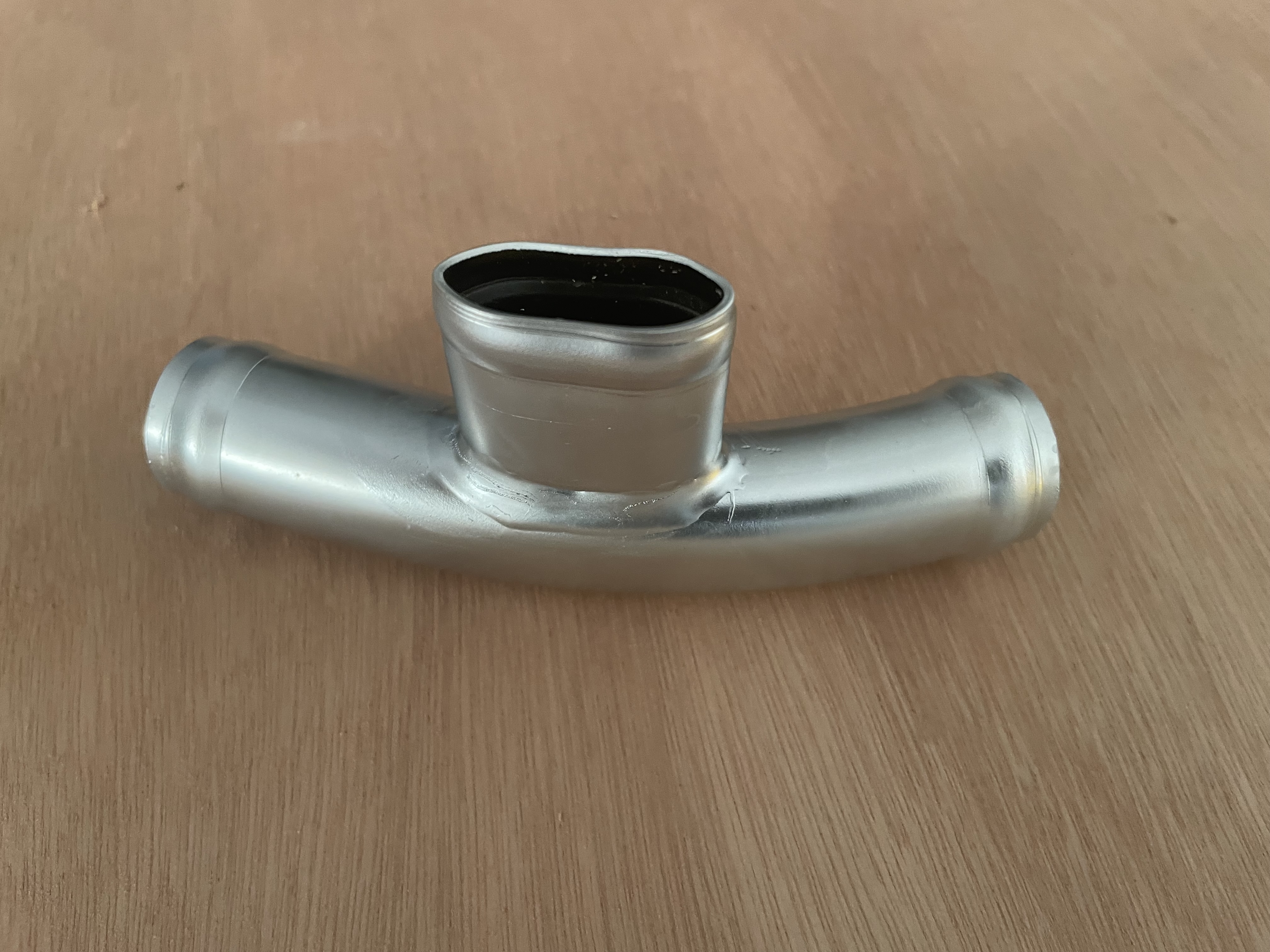
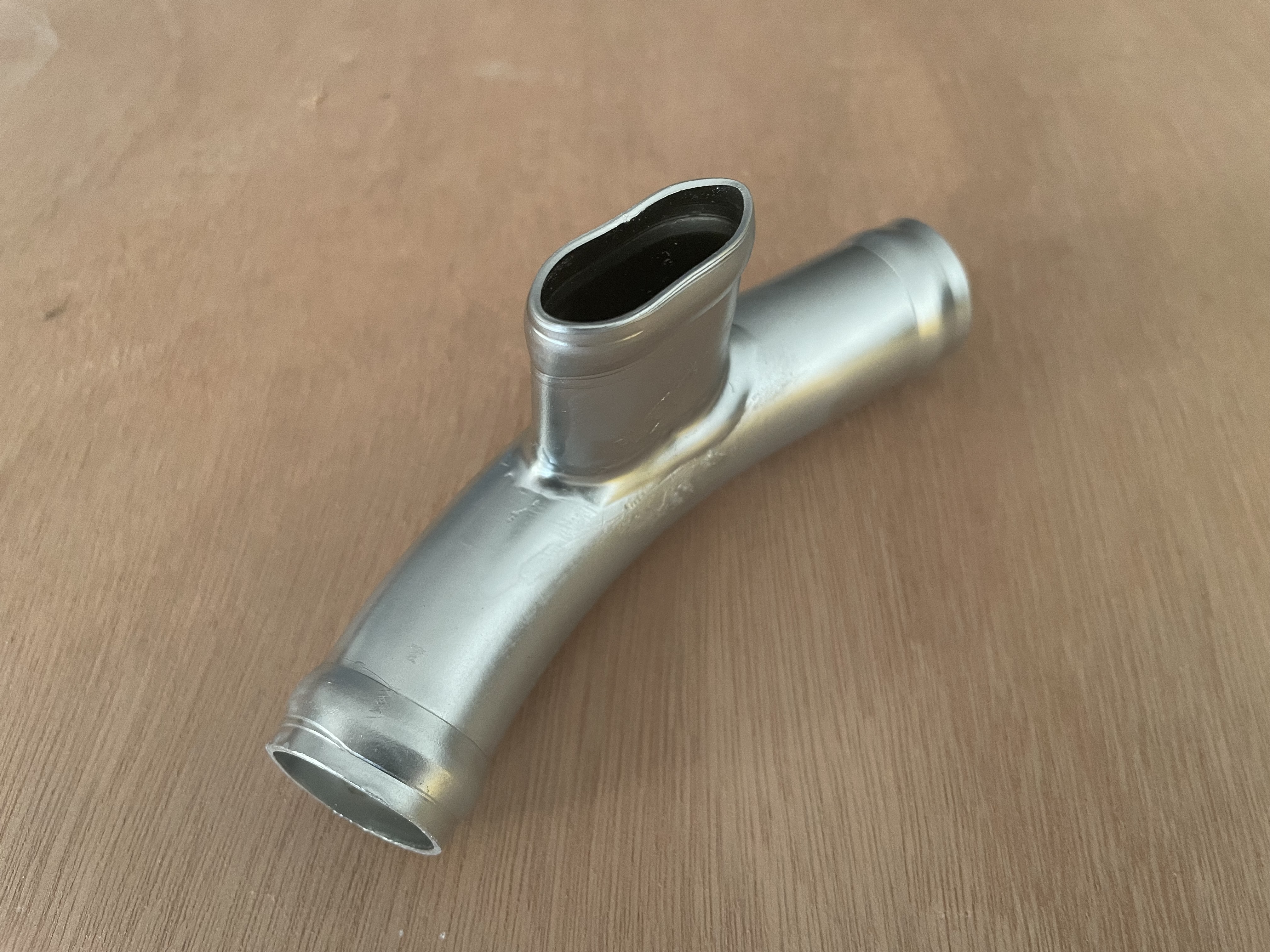
After rebuilding the mouthpiece nozzle, I wanted to experiment a special painting having an aesthetic effect similar to that of galvanic chrome plating. The result, which I considered acceptable, avoided me in sending the nozzle for chrome plating to a specialized company with the related costs and lead times. Not having to resist in the sea water environment typical of scuba diving, I thought that this solution was compatible with the use of the component for display purposes only. The final result is shown in Figure 31 and Figure 32.
 |
 |
| Figure 31 |
Figure 32 |
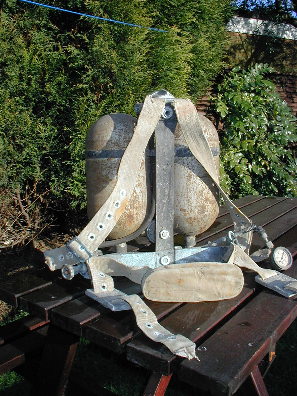
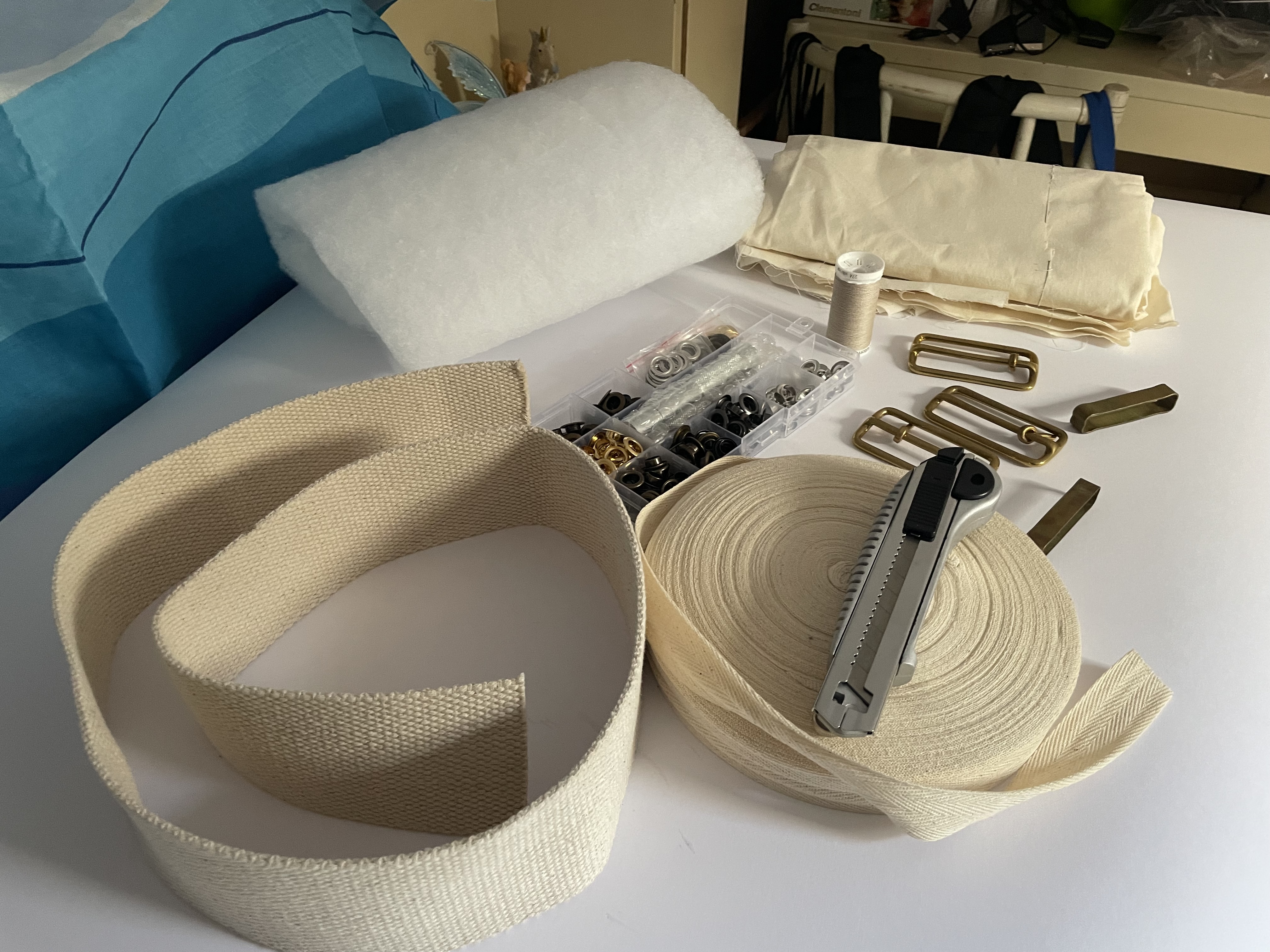
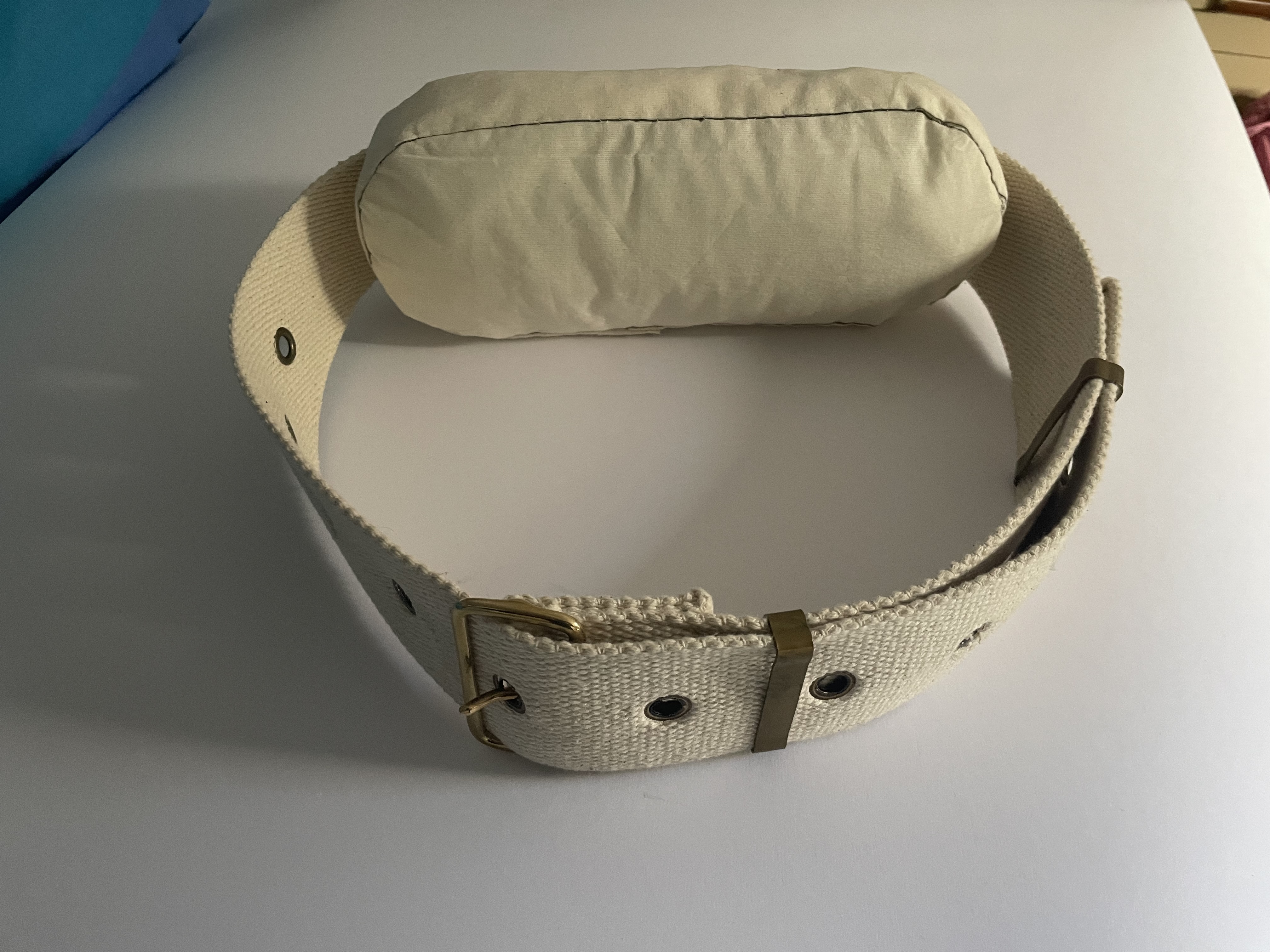
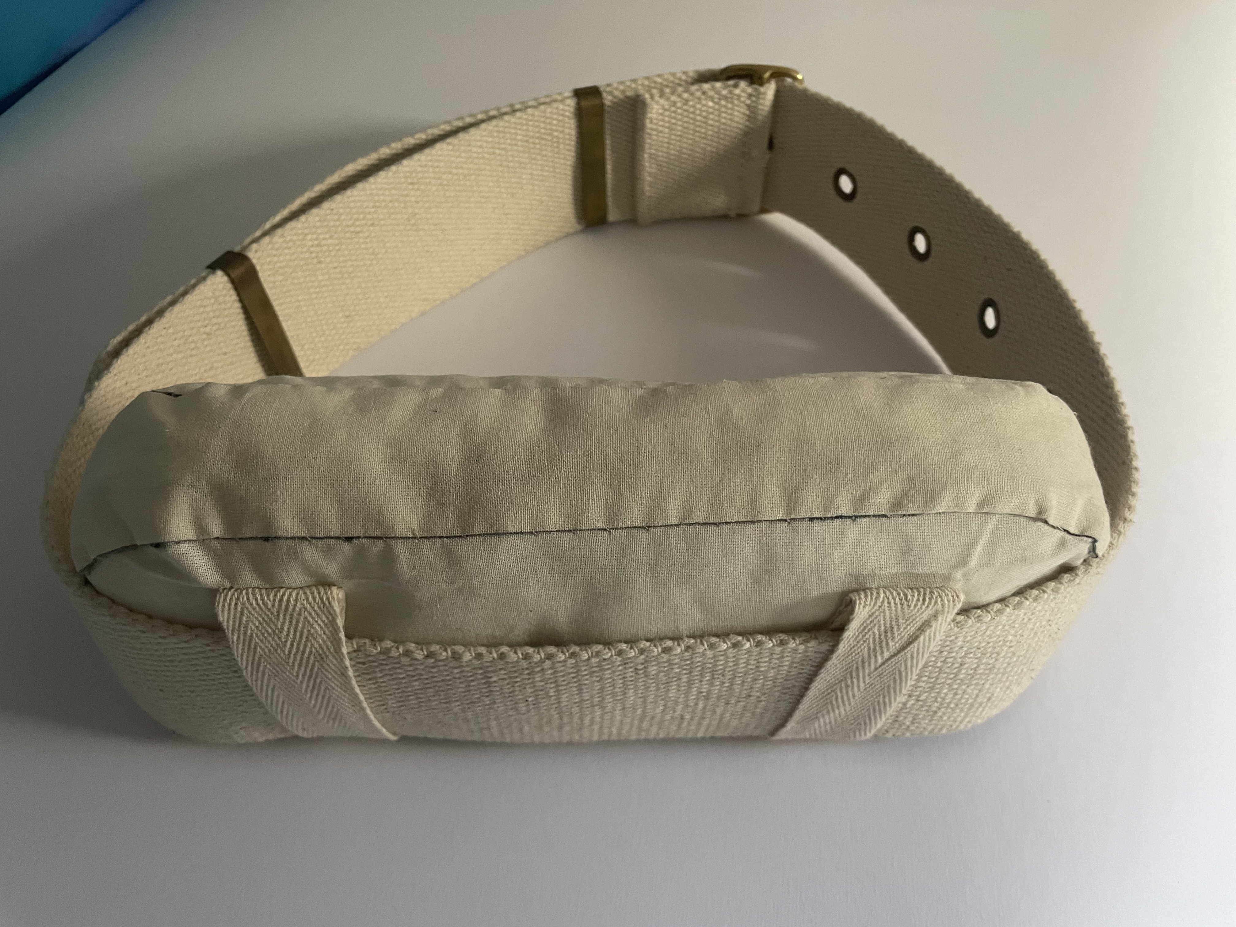
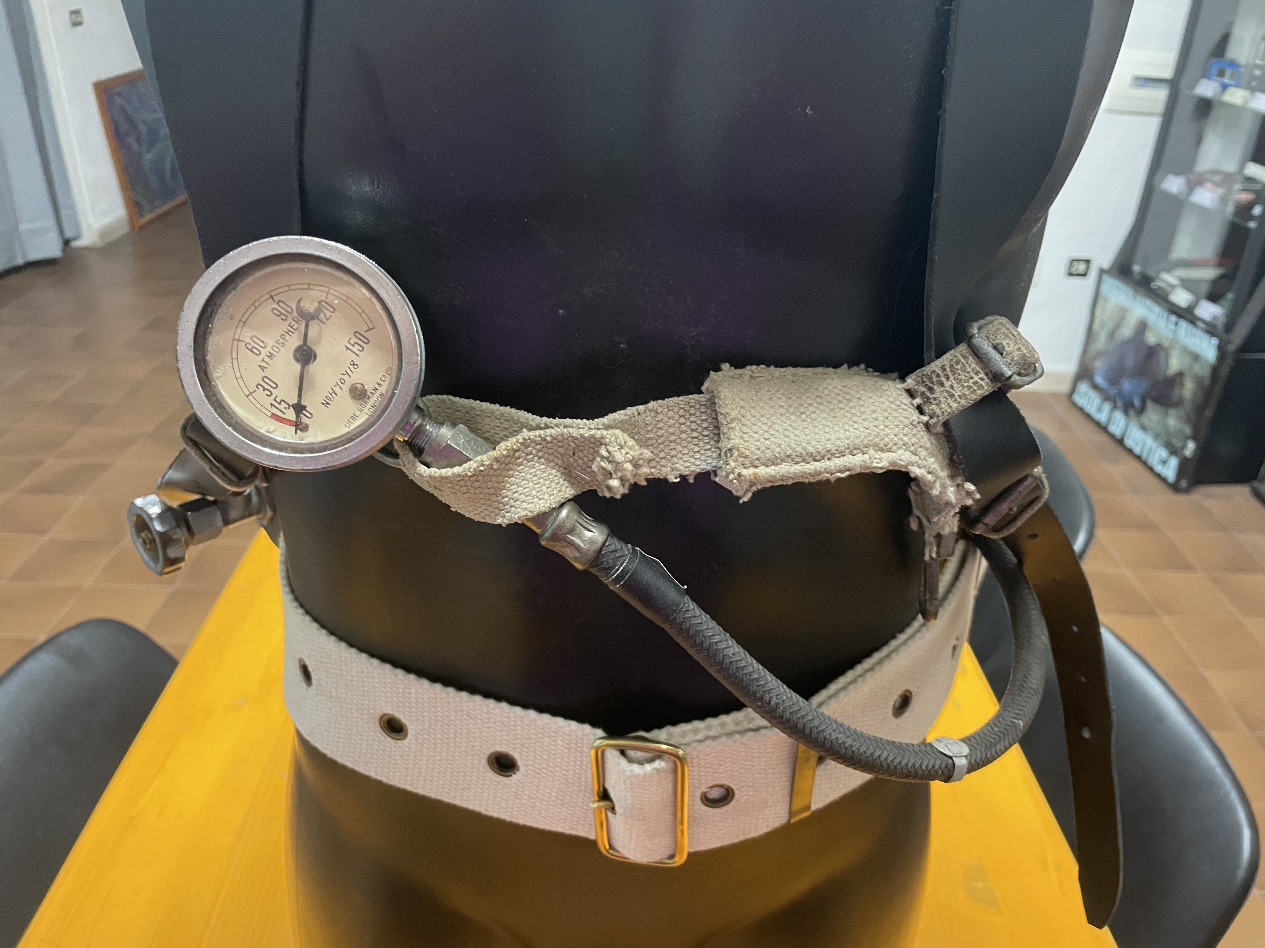
The other missing component in the sample purchased by the French collector was the ventral belt which, as I understood analysing the photos received from HDS - UK, was manufactured using a military-type fabric belt having a width of 63 mm (approximately 2.5 inches). The classic bronze buckles and eyelets were then mounted on the belt for its adjustment according to the size of the diver and the thickness of the worn suit. In addition, I have noticed the existence of a specific padded cushion, also made in fabric, to be inserted in the central area between the belt and the supporting frame of the “Tadpole”, to avoid annoying contacts between this frame and the diver’s back (see Figure 33). Also in this case, all the necessary material (see Figure 34) was found on eBay and in the end it was mainly a job of cutting and sewing. The final results can be appreciated in Figure 35 and Figure 36.By the observation of the differences between my sample and that of the HDS – UK museum, but also on the basis of the knowledge acquired during previous restorations of SCUBA regulators from Siebe Gorman, I found that the screw clamps used to tighten the connections between the corrugated hoses (installed between the second stage and the mouthpiece nozzle) and between the smaller section pipes (installed between the by-pass valve and the second stage and between the first and second stage) were added later and are different from the original solution.
 |
 |
| Figure 33 |
Figure 34 |
 |
 |
| Figure 35 |
Figure 36 |
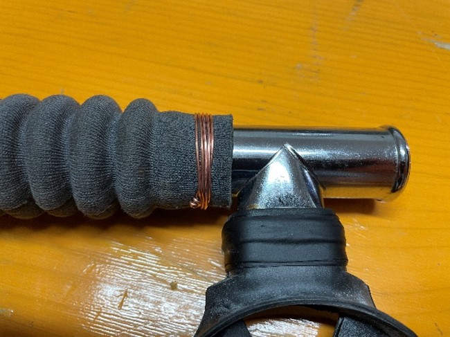
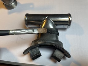
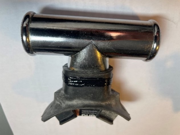
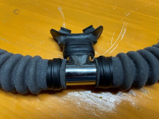
This consisted in tightening the hoses to their outlets by copper wires, wrapped around the hoses ends and finally tensioned by pliers. Then these connections were normally sealed by covering them with self-vulcanizing rubber tape. For the connection between the rubber mouthpiece and the nozzle, a textile thread was used which was then sealed with epoxy resin (see Figure 37, Figure 38, Figure 39 and Figure 40 taken from a previous restoration of a Siebe Gorman EssJee Aqualung MK I SCUBA regulator).
 |
 |
| Figure 37 |
Figure 38 |
 |
 |
| Figure 39 |
Figure 40 |
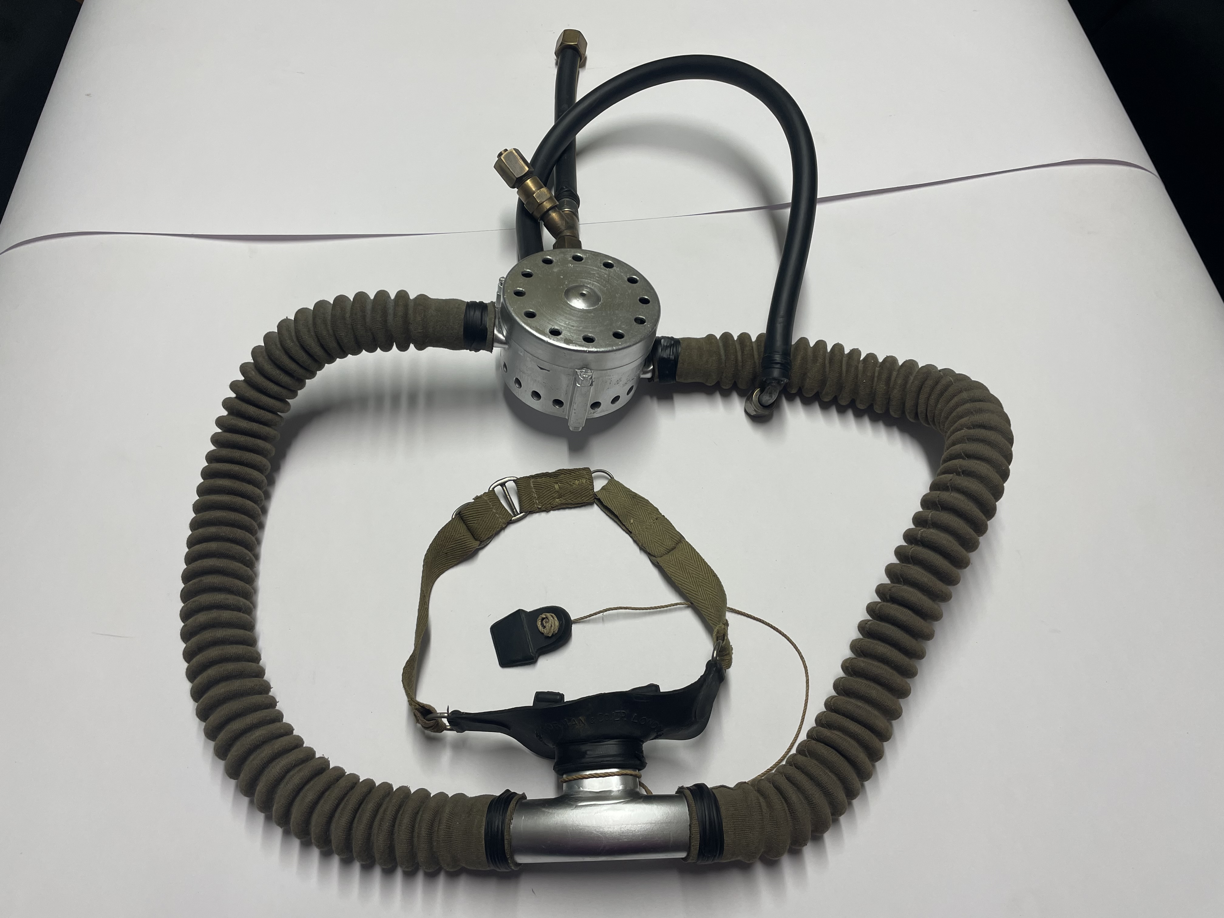
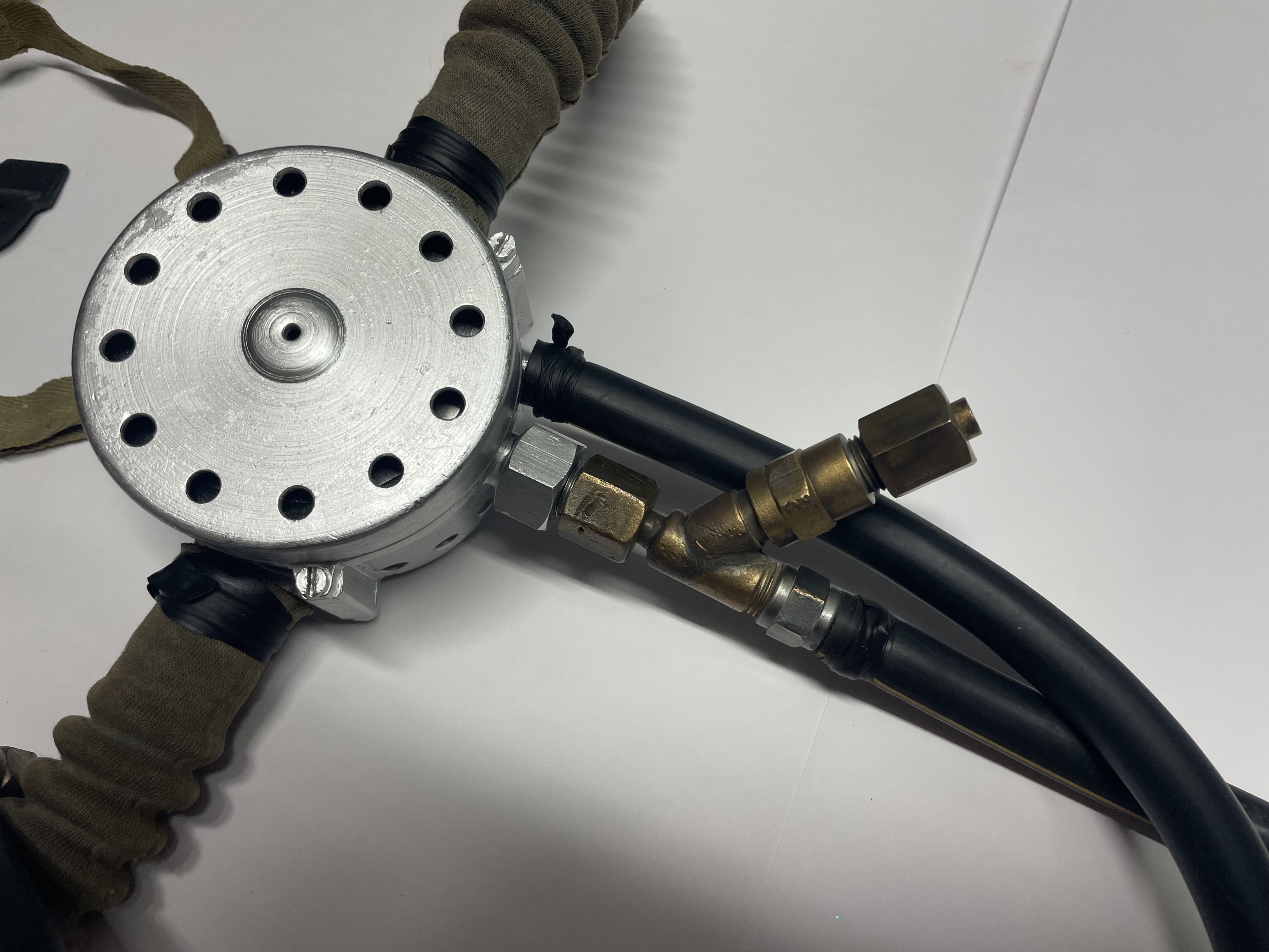
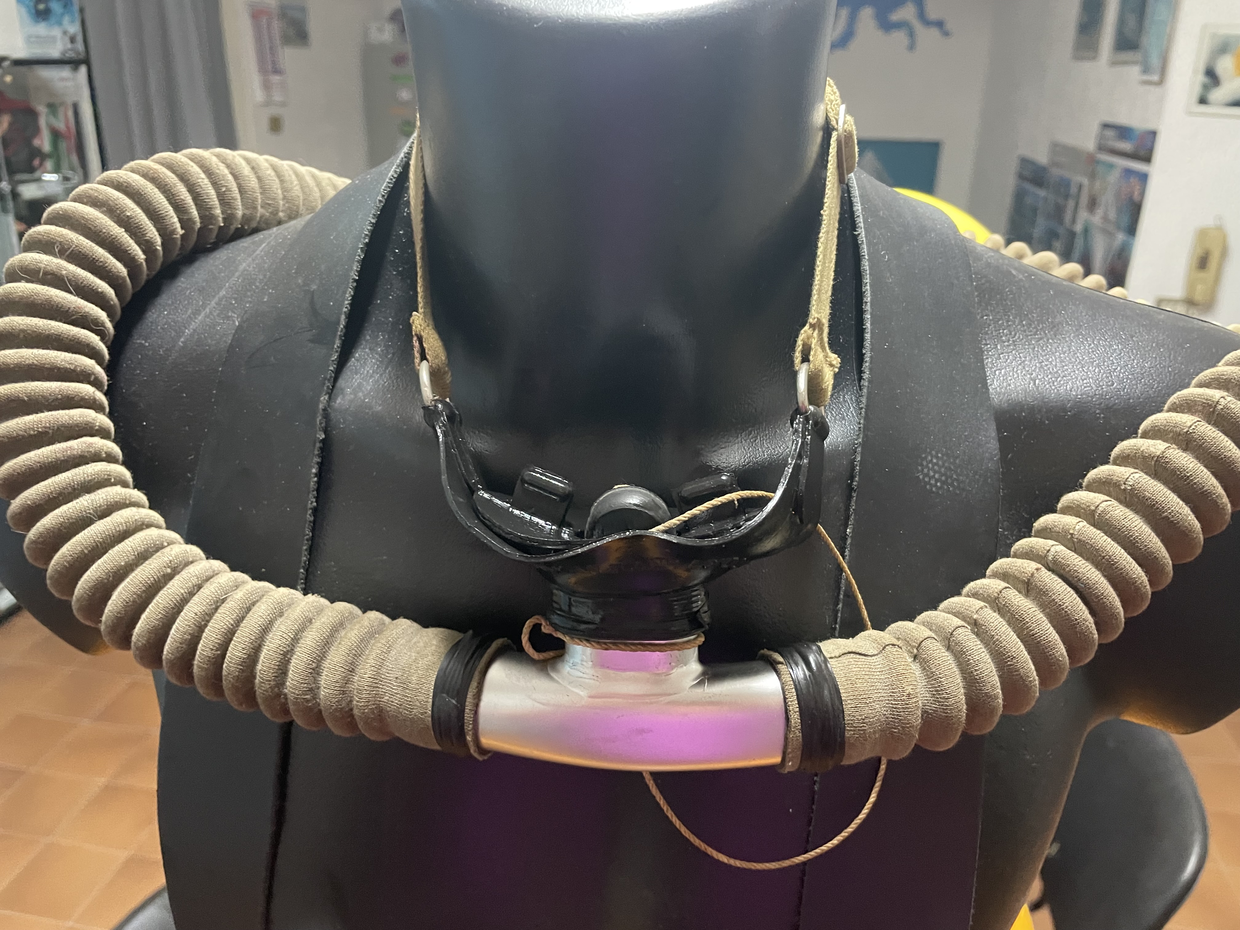
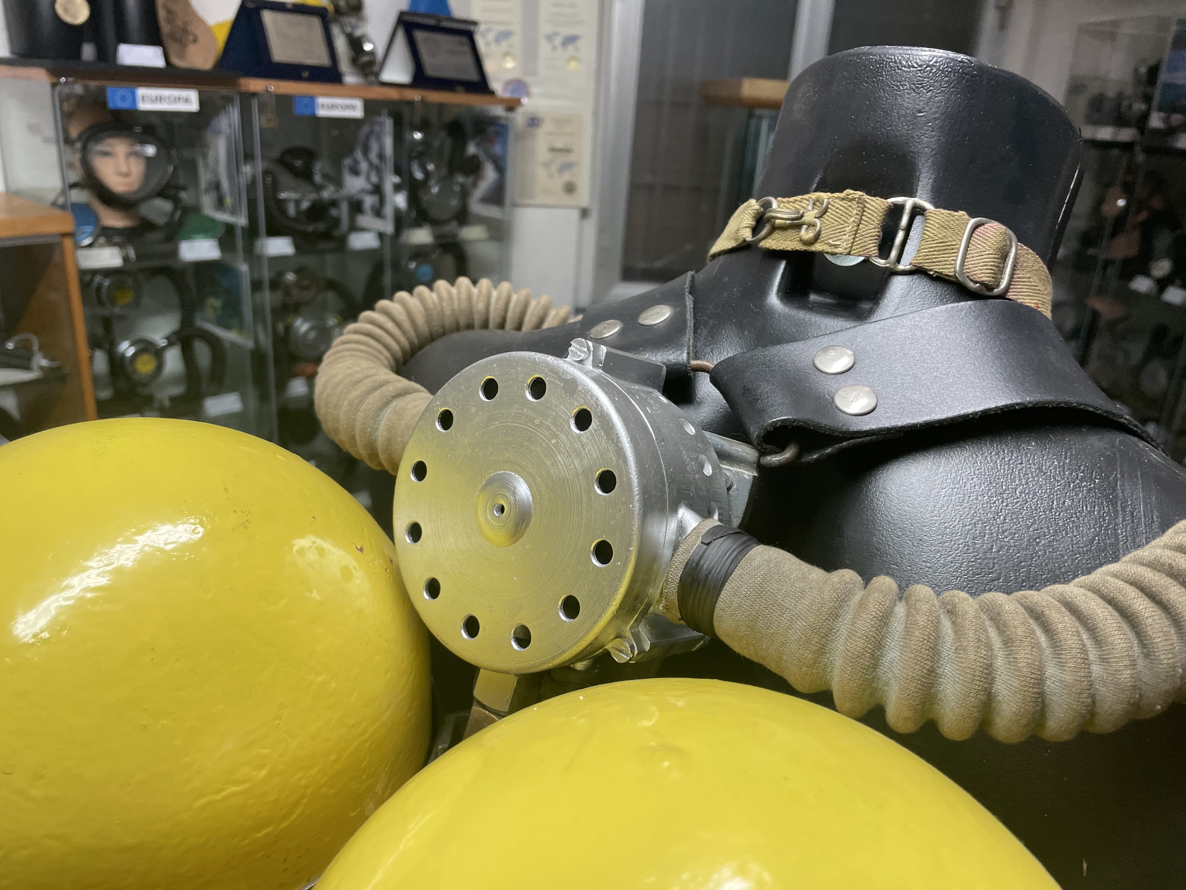
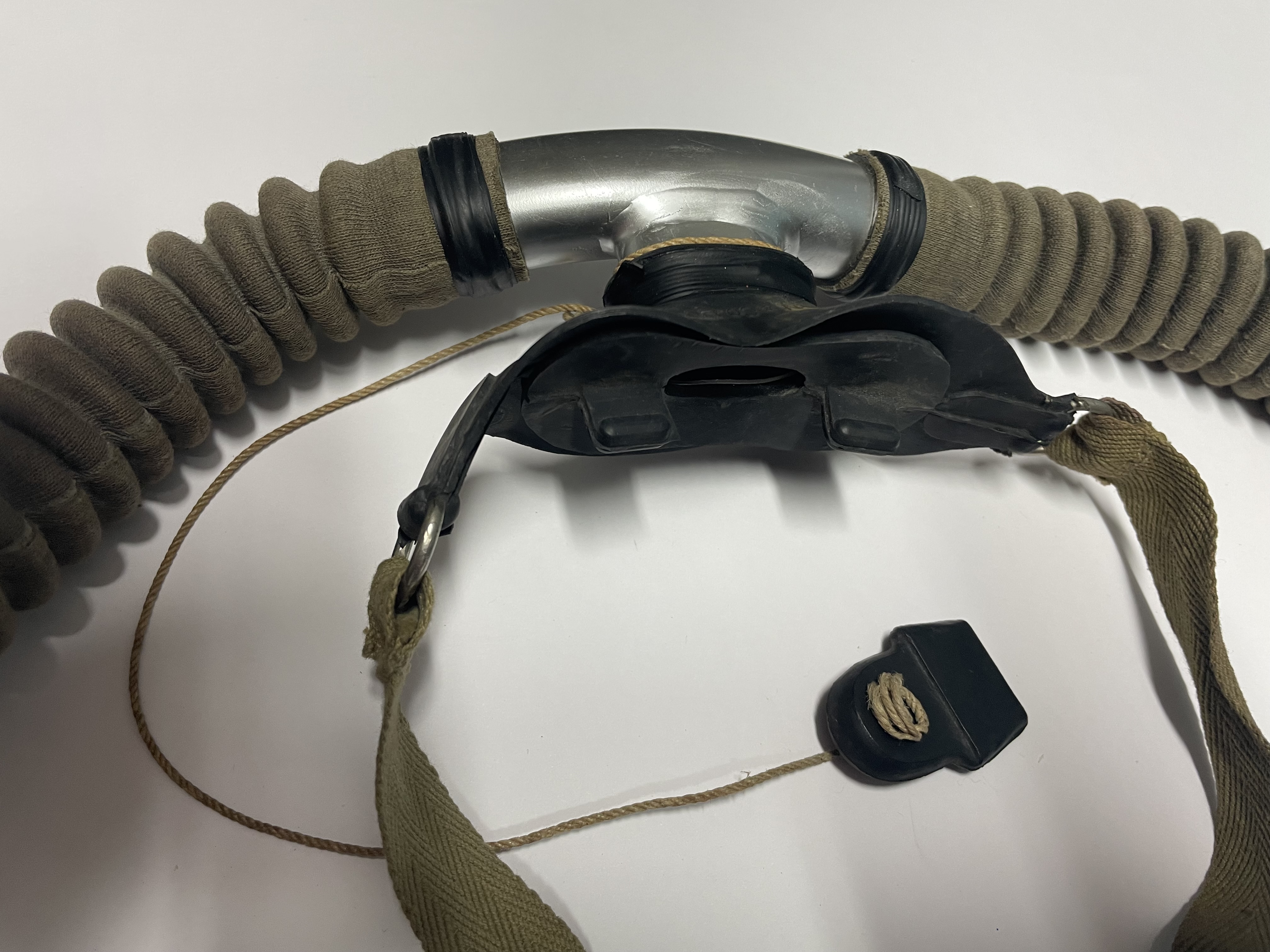
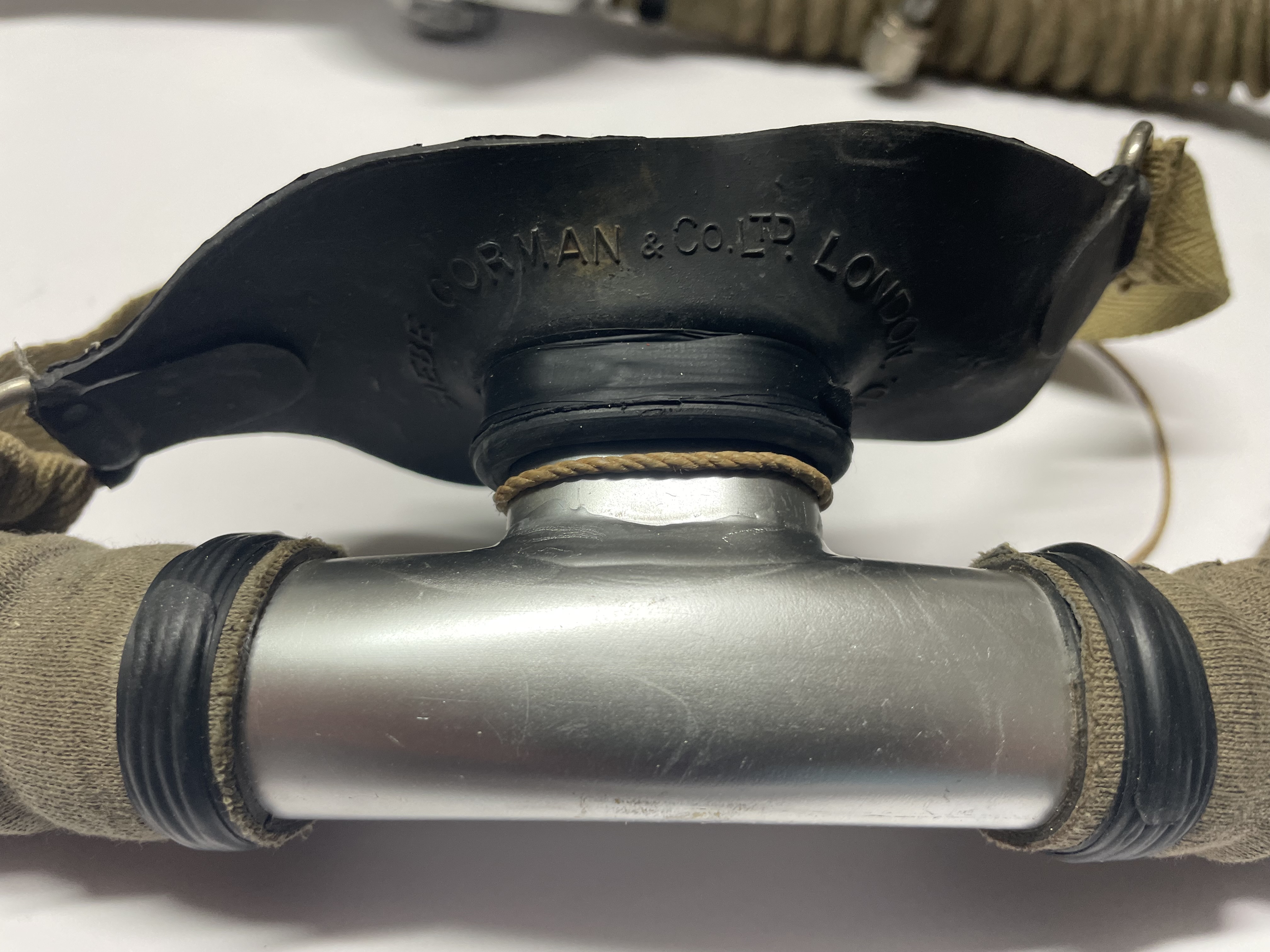
I therefore decided to use the same techniques also on my "Tadpole" sample, obtaining the results that are shown in Figures 41, 42, 43, 44, 45 and 46. As can be seen from the aforementioned figures, in the rebuilding work I used the original rubber mouthpiece of the "Salvus" oxygen rebreather providing the writing "Siebe Gorman and Co. Ltd London" and equipped with an operator’s neck retention strap (which was a standard solution on many underwater breathing apparatus in that period) and a rubber closing plug secured the body of the mouthpiece by a safety rope.
 |
 |
| Figure 41 |
Figure 42 |
 |
 |
| Figure 43 |
Figure 44 |
 |
 |
| Figure 45 |
Figure 46 |
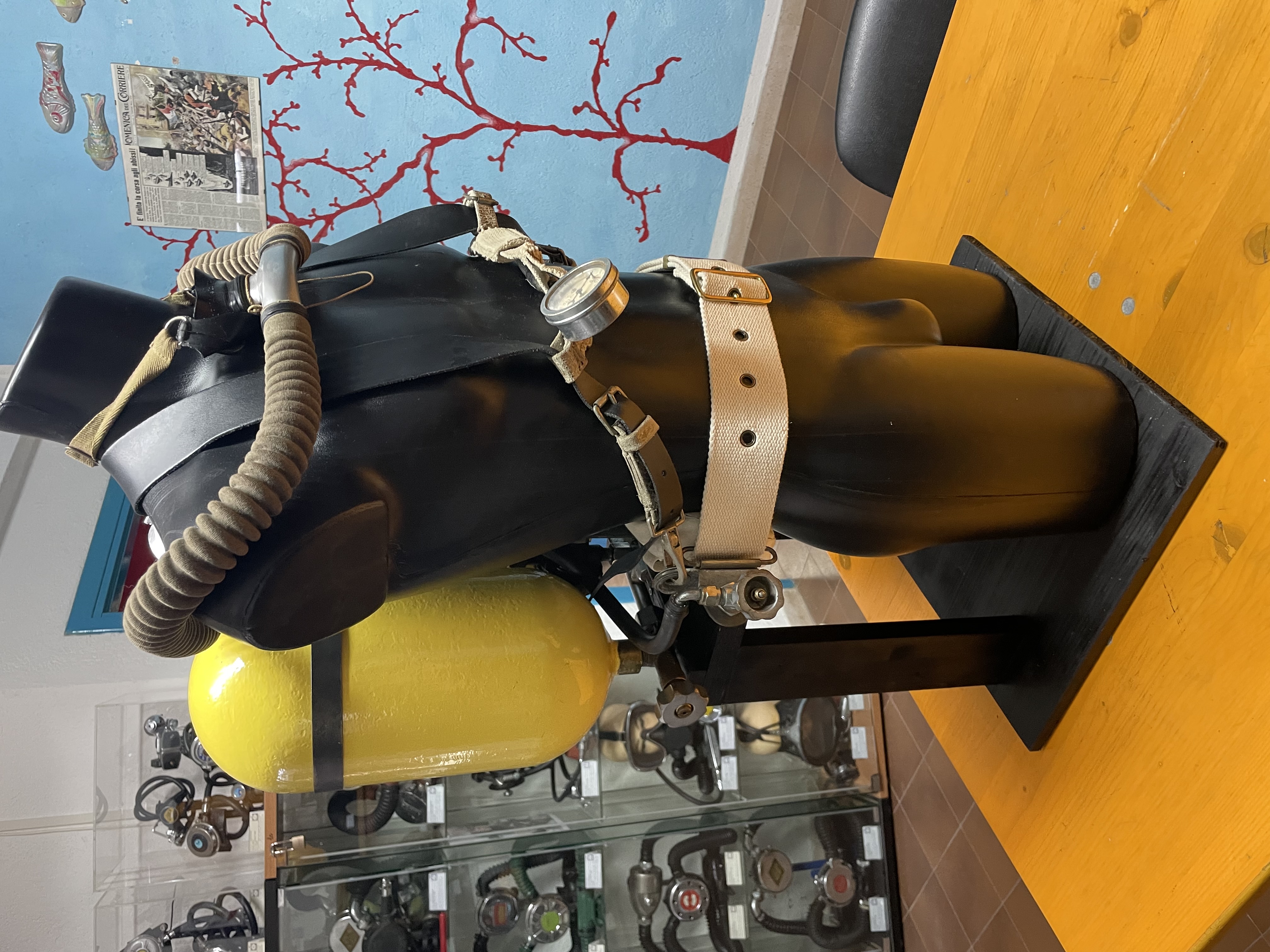
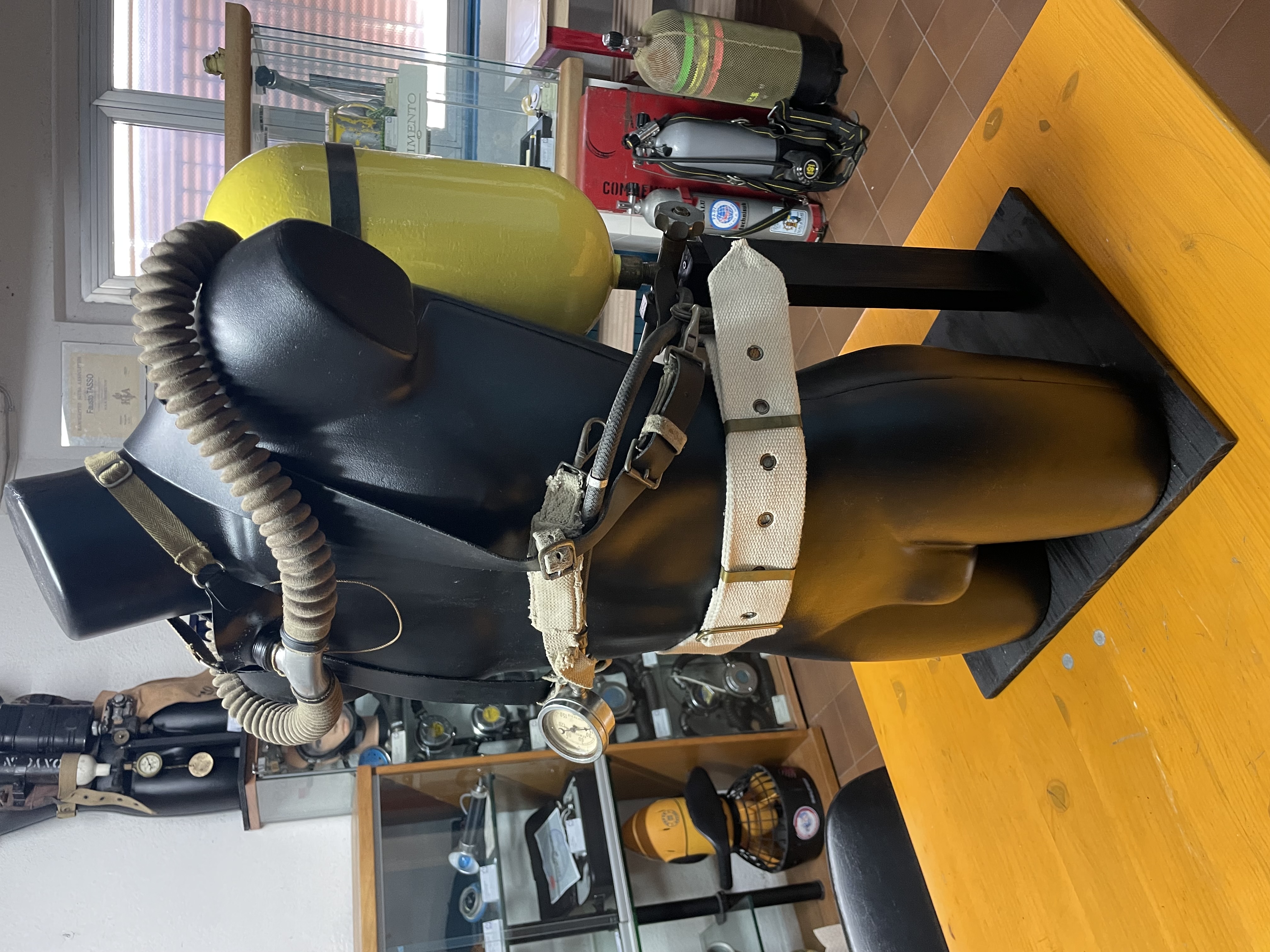
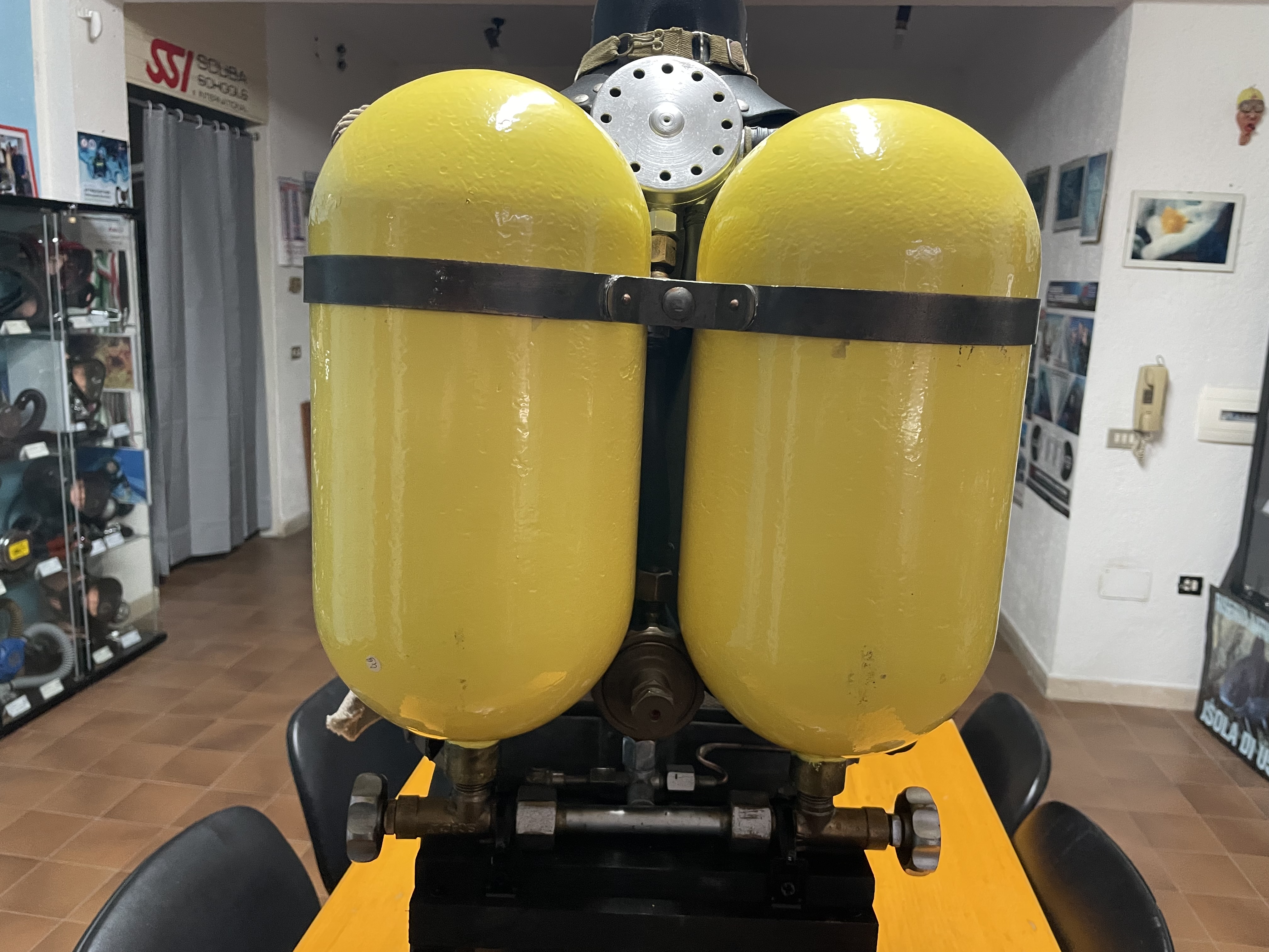
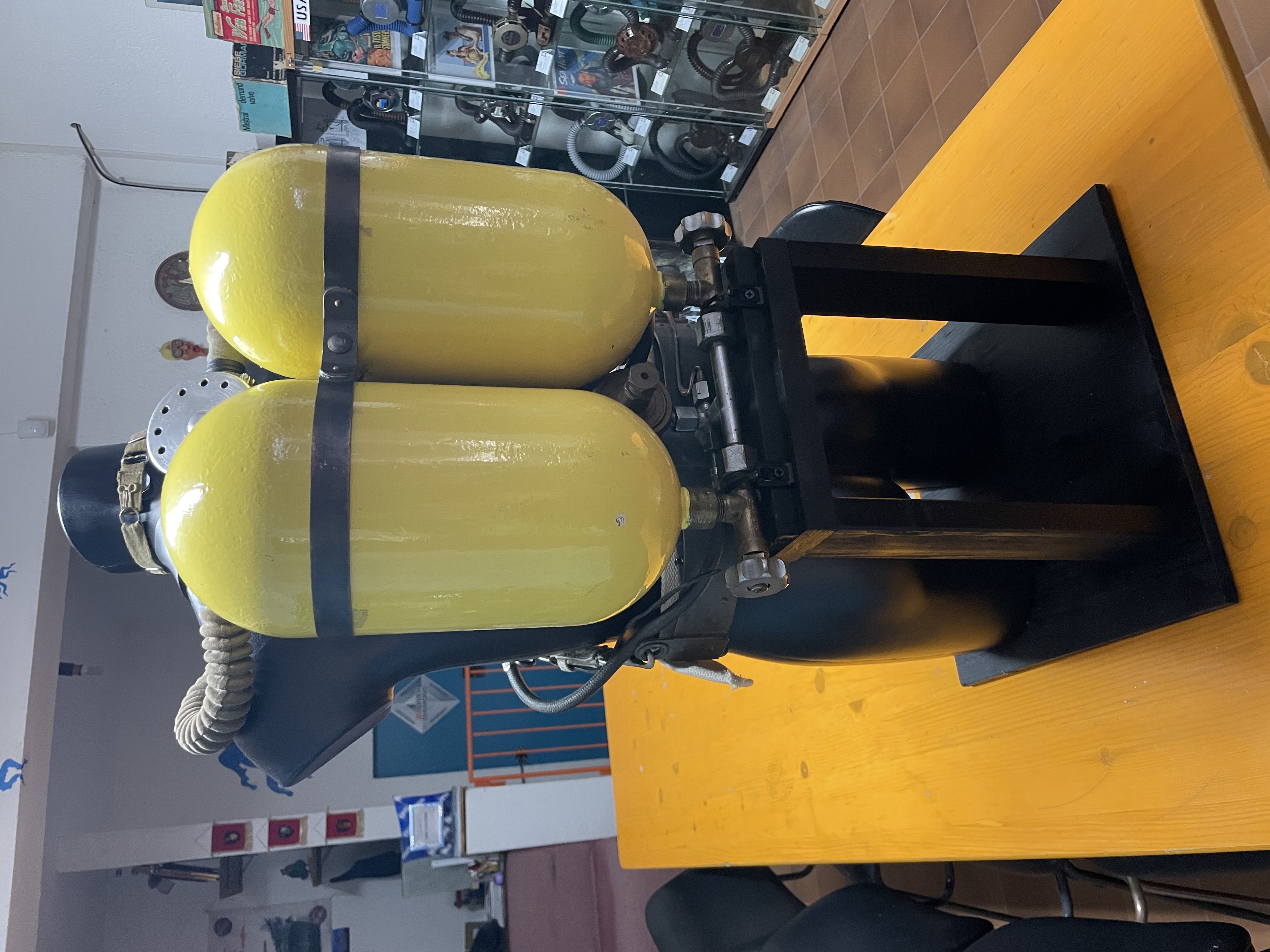
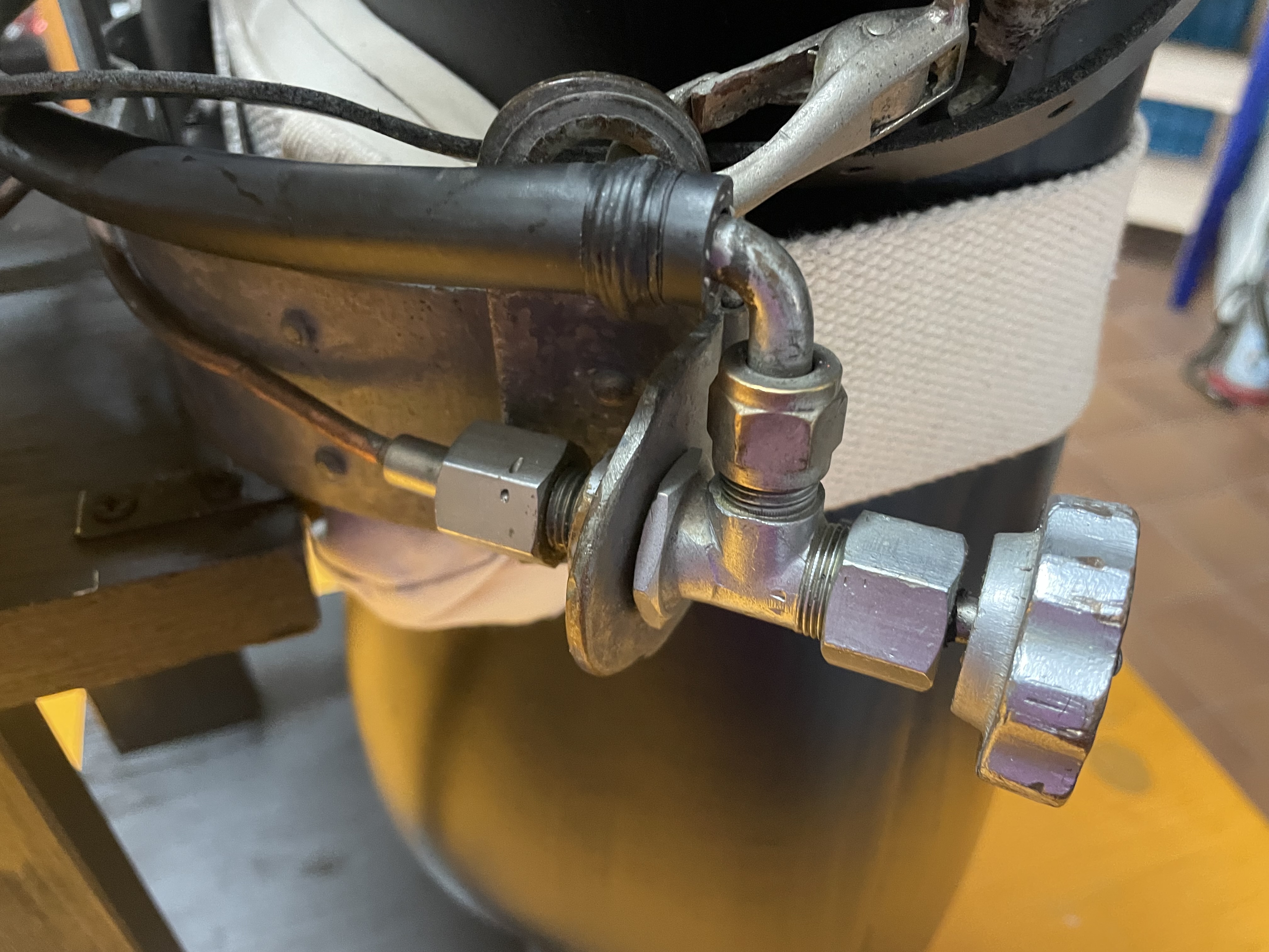
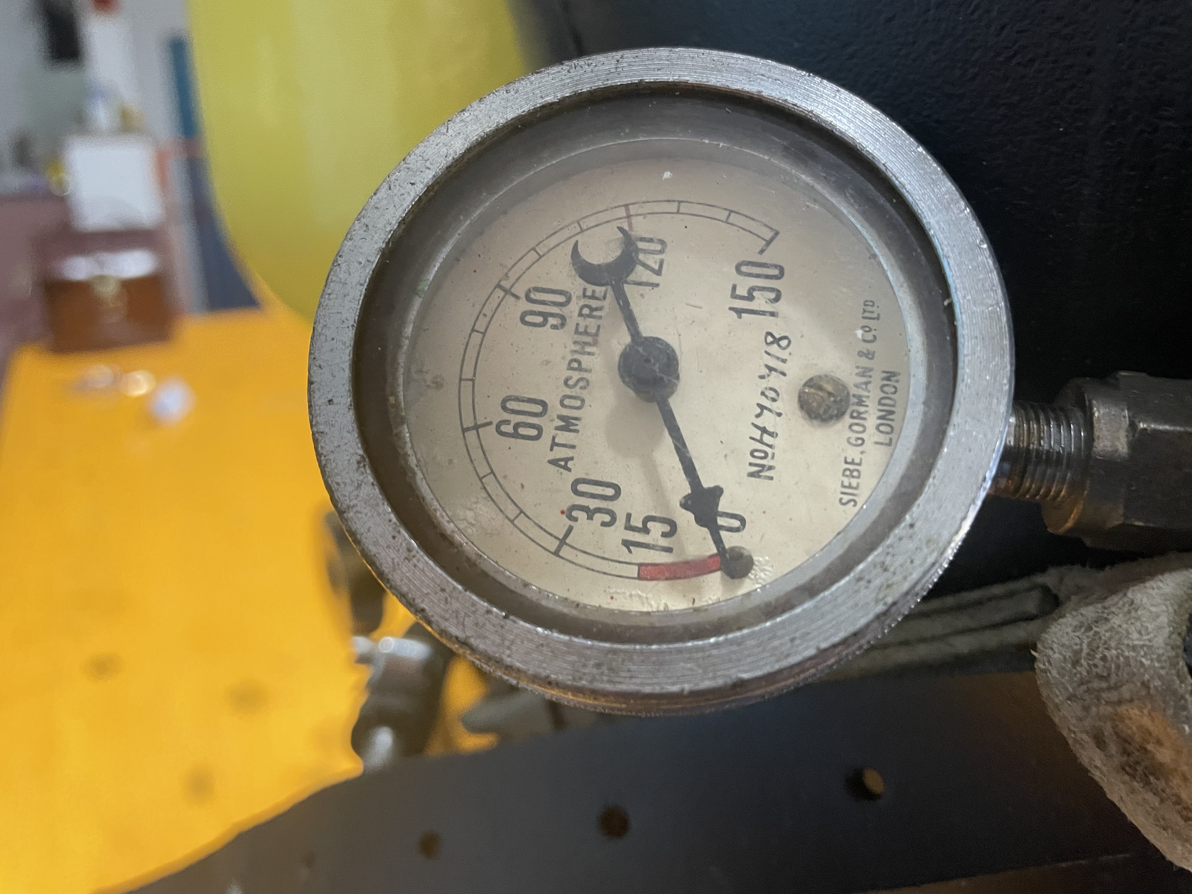
In Figure 42 the "Y" connection which was used for the possible air feeding of the “Tadpole” set from the surface (Hookah) is clearly visible. I have now been able to completely reassemble the unit with the modified or rebuilt materials and components and the final result can be seen in Figures 47, 48, 49, 50, 51, 52, 53 and 54.
 |
 |
| Figure 47 |
Figure 48 |
 |
 |
| Figure 49 |
Figure 50 |
 |
 |
| Figure 51 |
Figure 52 |
 |
 |
| Figure 53 |
Figure 54 |
This restoration work was long, complex and also quite expensive and requested to partially sacrifice a "Salvus" unit from my collection in order to obtain the components to be modified and used on my "Tadpole". However, I am convinced that it was worthwhile based on the awareness and the satisfaction of having brought one of the very few still existing examples of this device back to a condition very similar to the original one and thus making it available to all enthusiasts of the history of diving who will have the opportunity to visit my permanent historical diving gear exhibition located in Gubbio.
_______________


