After completing my latest project—creating a replica (non-functional and for display purposes only) of the only surviving prototype of the Cousteau-Gagnan regulator (specifically, the CG-45 prototype owned by Aqualung France), a project that resulted in an article published in the “Equipment Restoration” section of Luigi Fabbri’s website www.blutimescubahistory.com and in issue 25-06/2026 of TauchHistorie magazine (published by HDS Germany)—I was convinced that my reconstruction work focused on the prototype phase of this famous scuba unit had come to a definitive end.
These experiences had started with the rebuilt of just the regulator assembly (first and second stages still non-functional and for display purposes only) of the “Scaphandre Autonome Air Liquide Systeme Cousteau” scuba unit, built by Émile Gagnan and used by Cousteau, Dumas, and Tailliez during the underwater filming of the 1943 documentary “Épaves” (Wrecks). This device is also known among collectors as the CG-43. The only surviving example of this apparatus is housed in the Frédéric Dumas Museum in Sanary-sur-Mer, a town on the French coast near Marseille (see Fig. 1 and Fig. 2).
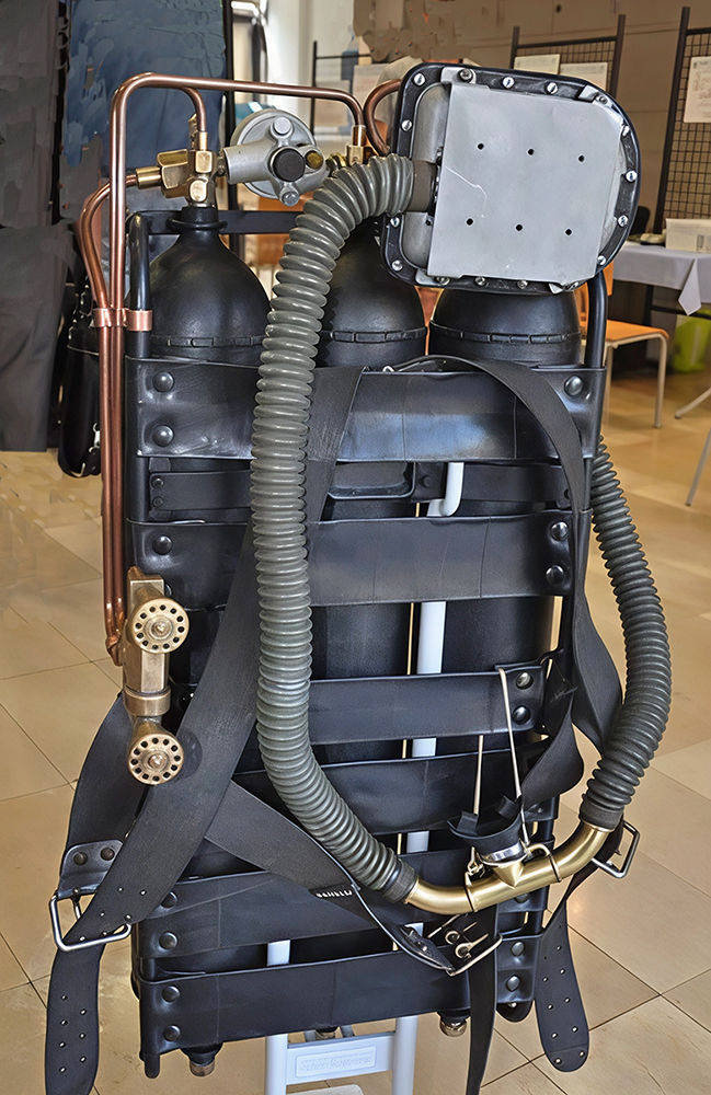
fig. 1 |
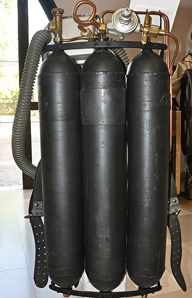
fig. 2 |
From this initial experience, I produced an article, also published in the “Equipment Restoration” section of Luigi Fabbri’s website www.blutimescubahistory.com and in issue 24-12/2025 of TauchHistorie magazine (published by HDS Germany). In this article I clearly stated that the rebuilt of the complete scuba set was beyond my capabilities for a number of reasons. The most important of these was the absence of almost all the unit's components. These parts had been recovered by the Dumas Museum staff from a wooden crate donated by the family of Robert Buffaz, a renowned diving pioneer and French spearfishing champion. It appears that Buffaz had received this material from Cousteau himself. The museum staff took the components from the crate and reassembled them to rebuild the complete breathing apparatus currently on display in Sanary-sur-Mer. Although some elements were missing and had to be recreated by the staff, the main components—such as first and second stages, cylinders, valves, and so on—were all available.
n my case, however, had I wished to produce a replica of the complete unit, I would have had to rebuild all its components (with the exception of the first and second stages, which I had already built). I would have had to do this without access to geometric measurements or detailed specifications for these parts, information I had previously received from a manager at Aqualung France, which had enabled me to faithfully replicate the CG-45 prototype they owned.
Unfortunately, however—as often happens when I leave a project I care deeply about unfinished—that familiar nagging thought took hold, prompting me to ask myself repeatedly: "Is this project truly impossible?" So, after receiving some detailed photos from the French collector friend mentioned in my previous articles (see a selection of these photos in Figs. 3, 4, 5 and 6), I reconsidered my position and ultimately decided to embark on this new adventure as well, fully aware of the technical challenges, the costs involved, and the long timeframe required to complete the project.
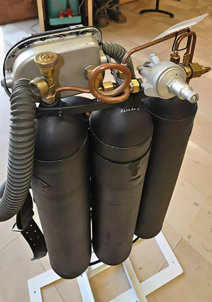
fig. 3 |
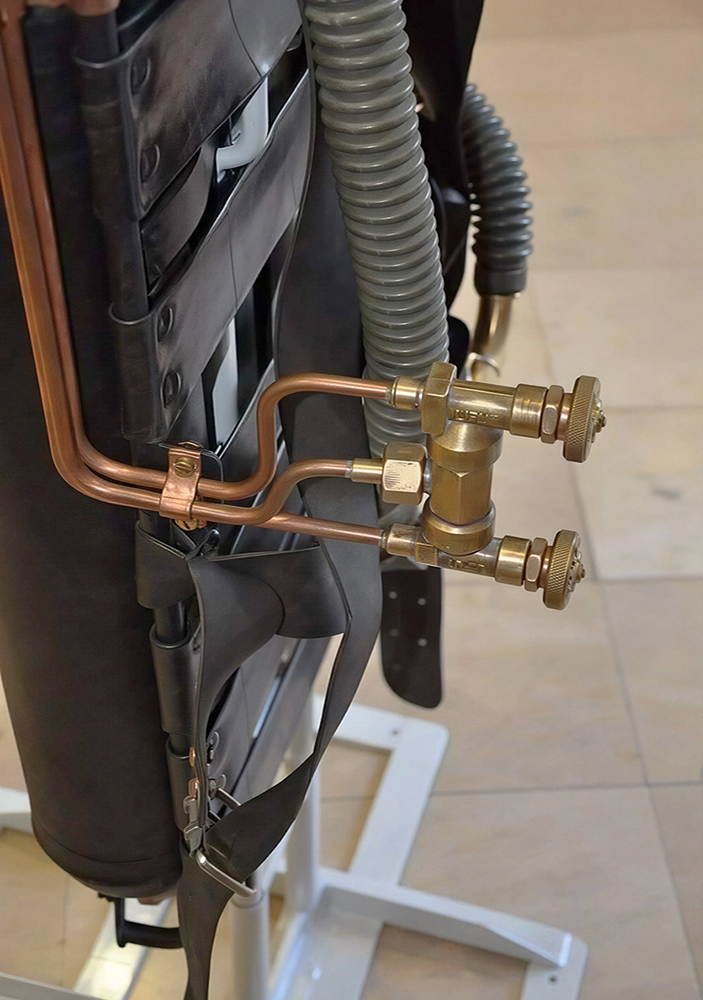
fig. 4
|
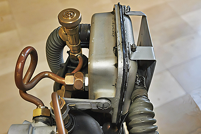
fig. 5 |
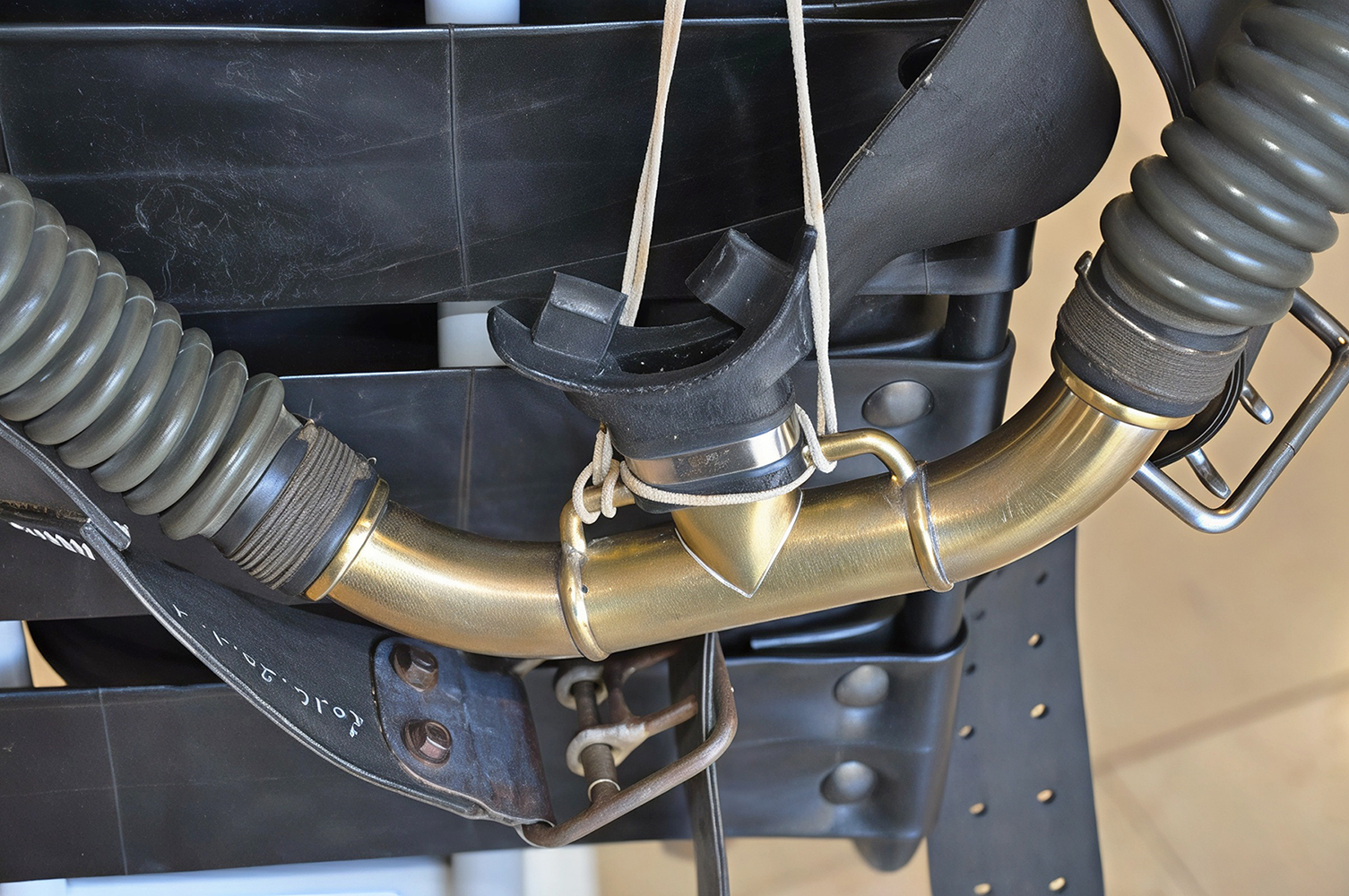
fig. 6 |
Regarding the primary challenge of lacking specific measurements and dimensions for the various elements making the complete scuba set, I decided to derive this information by analysing the available photos. The dimensions of the parts I needed to manufacture—measured directly from the photos using a ruler and a vernier caliper—were determined through simple proportional calculations based on components with known geometric data (such as the previously rebuilt second stage and mouthpiece, or the cylinders, for which a French collector friend had provided the outer diameter and total length). For parts with standardized dimensions that I had identified and purchased to complete the project (e.g., valves, pneumatic circuit fittings and adapters, copper tubing, fasteners, etc.), the measurements were readily available in the relevant technical data sheets.
After gathering this information, producing the corresponding dimensioned sketches, and studying the prototype's installation details, I created a 3D virtual CAD model of the assembly, comprising the three cylinders and the steel frame connecting them to the harness. Several views of this model are presented below. Specifically, Figs. 7 and 8 show front and rear axonometric views, Fig. 9 shows a rear view, and Fig. 10 shows a top view.
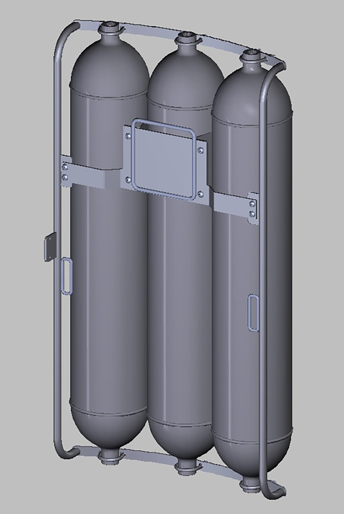
fig. 7 |
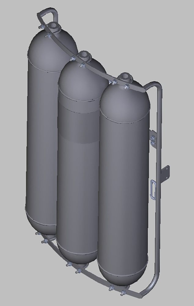
fig. 8 |
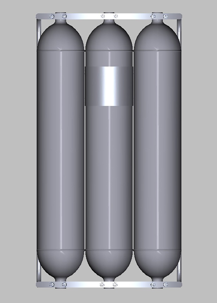
fig. 9 |
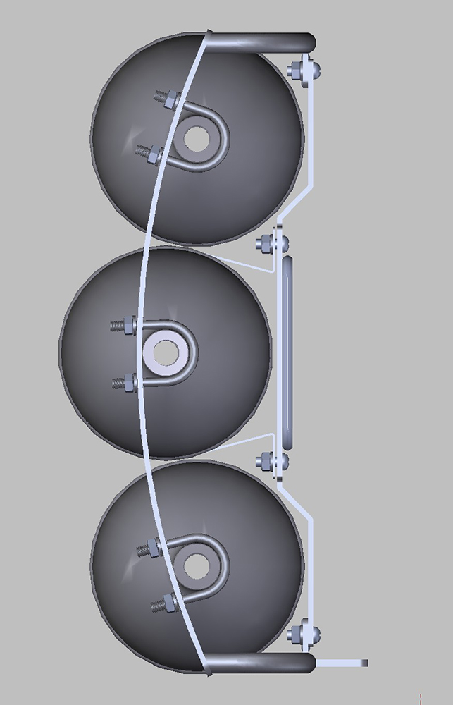
fig. 10 |
The first major components produced were the three 5-liter tanks; as can be seen in the previous photos, these feature a double-dome design welded to a cylindrical central body. Off course, the tanks I needed to create only had to be visually identical to the originals, with no requirement to actually hold compressed air.
Therefore, the end caps were modeled using CAD (see Fig. 11) and then produced in resin via 3D printing (see Fig. 12).
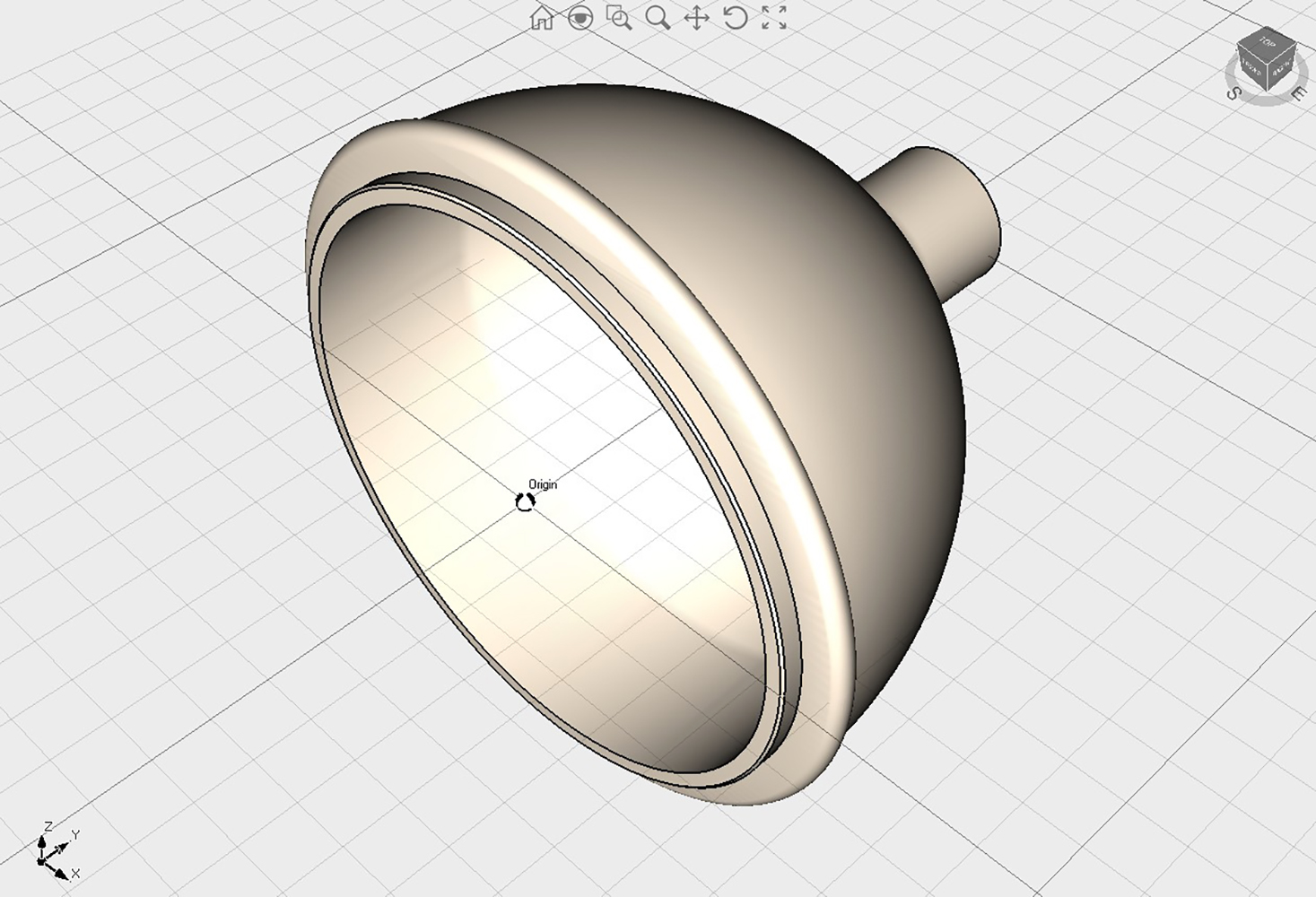
fig. 11 |
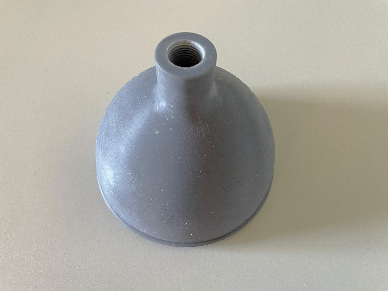
fig. 12 |
The central cylindrical body consists of an aluminum tube with an outer diameter of 120 mm, a wall thickness of 5 mm, and a total length of 500 mm. The three tubes were purchased online from a supplier of row metal products.
The resin end caps, featuring internal machining to ensure alignment with the cylindrical aluminum bodies, were permanently secured to the latter using two-component epoxy adhesive (see Figs. 13 and 14).
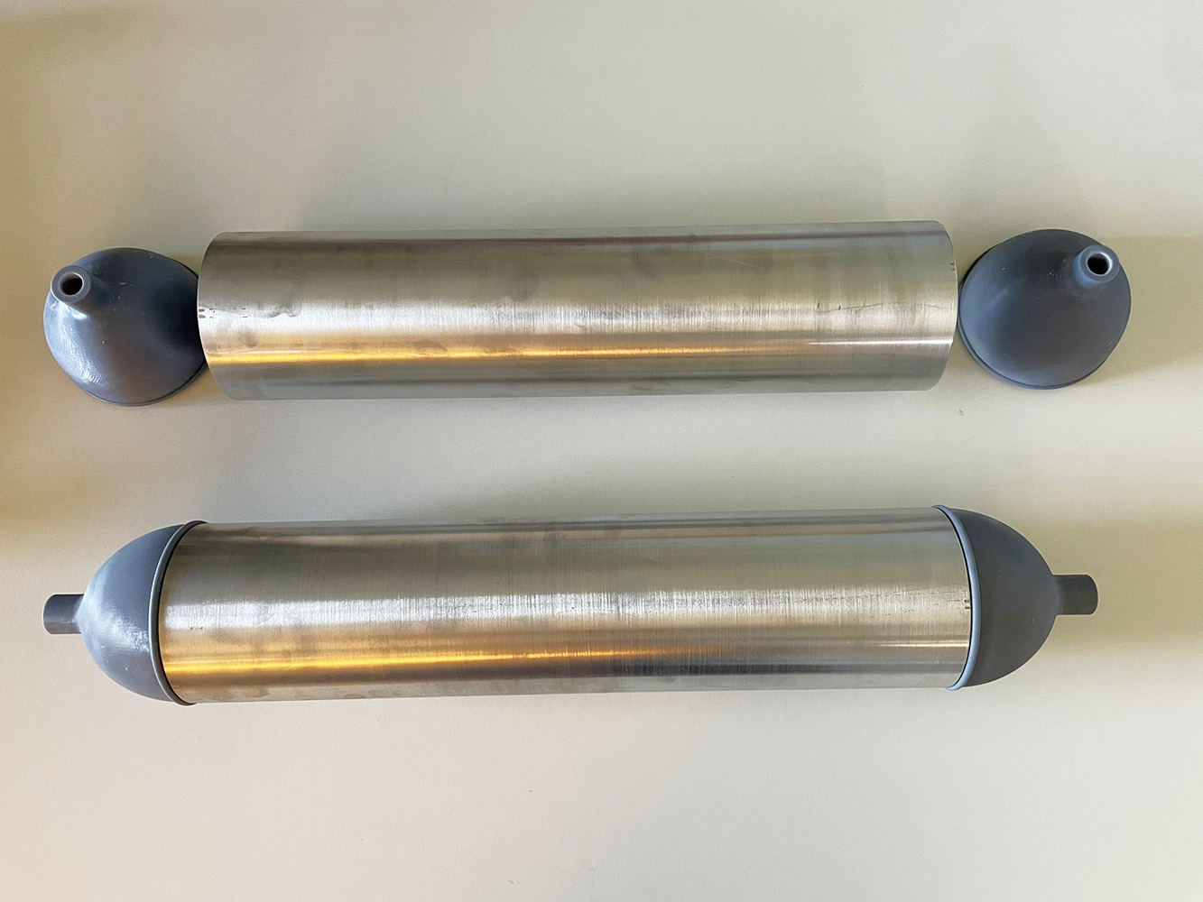
fig. 13 |
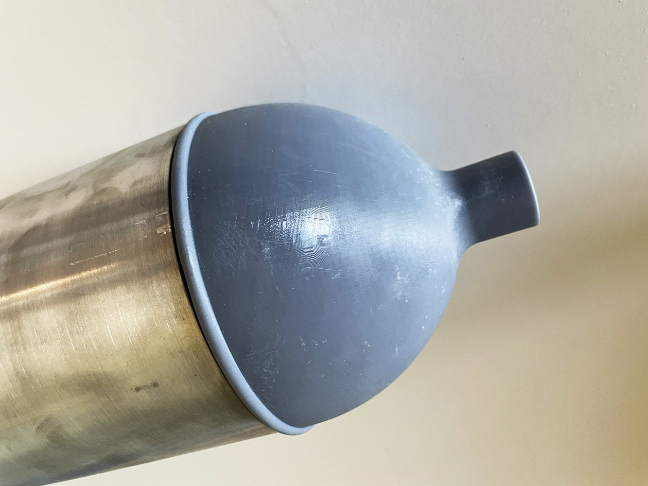
fig. 14 |
The bonding process was correctly carried out using a clamp of a length compatible with the complete cylinder (see Fig. 15). After bonding the end caps, the cylinders were filled, sanded, and finally painted (see Fig. 16).
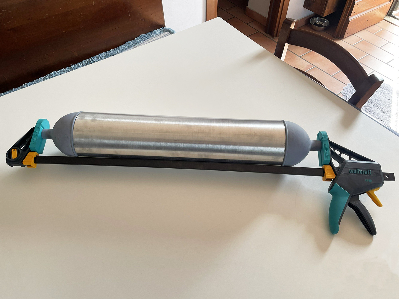
fig. 15 |
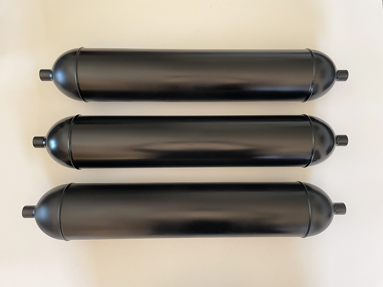
fig. 16 |
Another key structural component of the prototype—the frame connecting the cylinders and the harness—was produced from stainless steel using various manufacturing techniques. Certain parts of the frame were realized from stainless steel sheets of different thickness, which were laser-cut and subsequently bent or rolled. Other frame elements were made from stainless steel bars of different diameters; these were also bent or rolled, then cut and machined to meet the design specifications. The various components produced in this way were then welded together using the TIG (Tungsten Inert Gas) process.
For the connecting band linking the frame to the central cylinder, an aluminum sheet was chosen over stainless steel to facilitate fabrication. Upon completion of the manufacturing process, the frame and the band were painted matte black—the same color used for the cylinders. The complete frame and several detailed views are shown in Figs. 17, 18, 19, 20, 21 and 22.
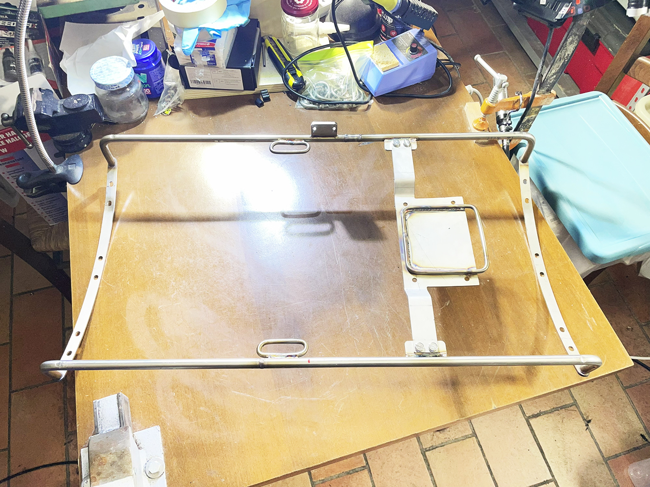
fig. 17 |
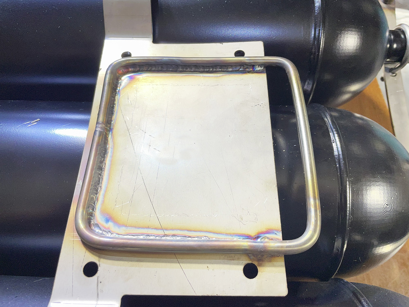
fig. 18 |
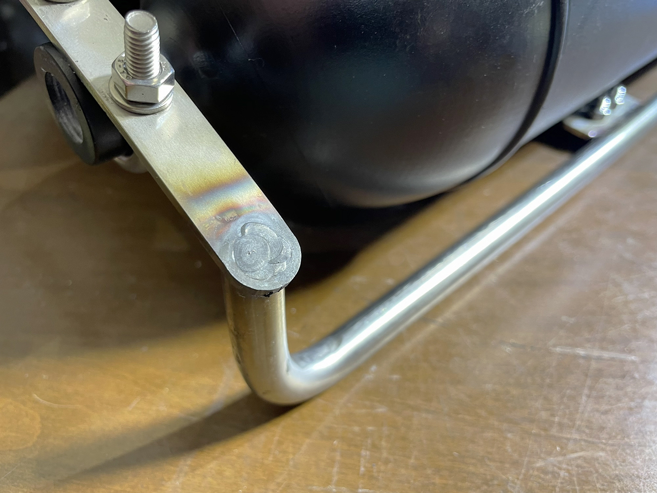
fig. 19 |
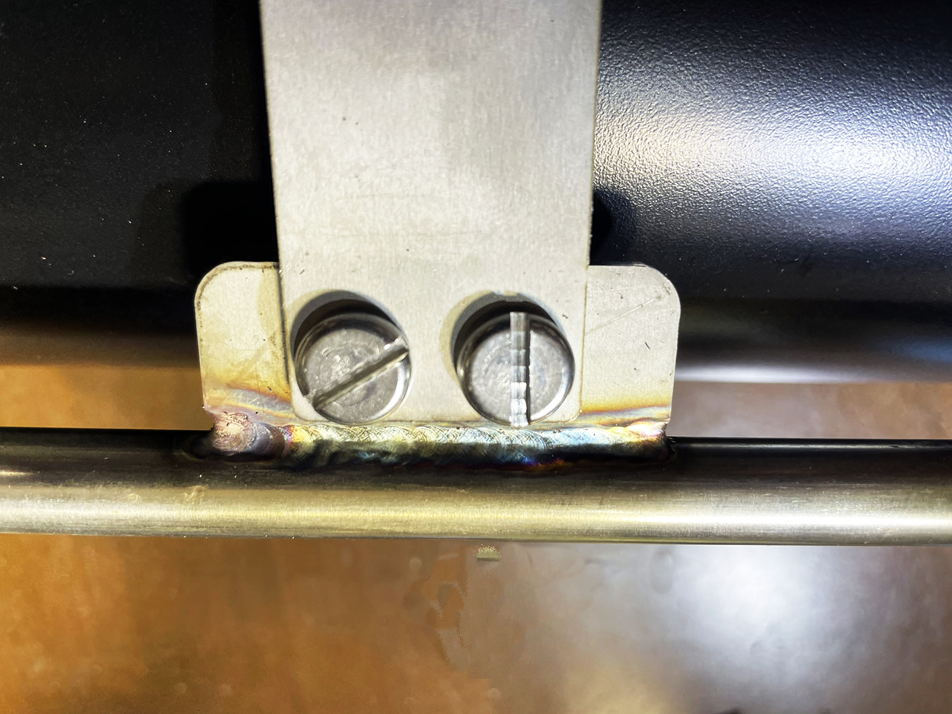
fig. 20 |
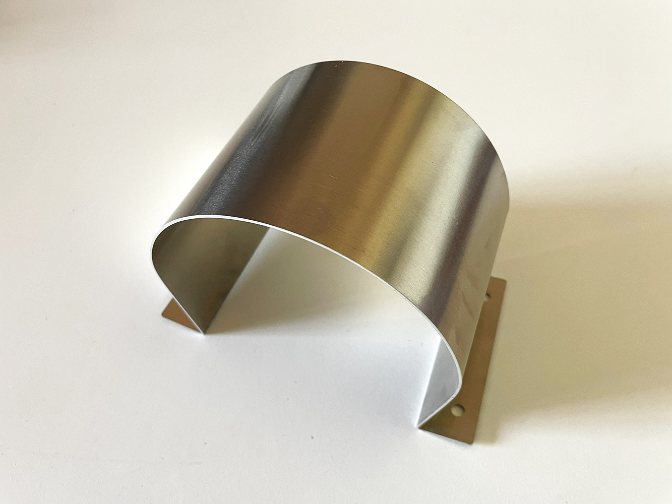
fig. 21 |
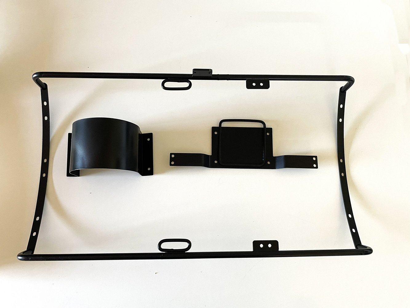
fig. 22 |
The manufacturing of the first and second stages of the scuba set presented no particular difficulties, as the process had already been established and tested through the creation of various replicas for collectors who had requested them (a process described in detail in the first of my previously cited articles). However, in this specific instance, the duckbill exhaust valve—which had been installed inside the second stage in earlier replicas—is now mounted on the outside of the cover, just as it is on the prototype in the Dumas Museum. This configuration requested the design and fabrication of a custom aluminum sheet-metal guard, which was mounted over the second-stage cover to protect the duckbill valve (see Figs. 23, 24 and 25). Off course, this guard is absolutely identical to the original one (see Fig. 1 and Fig. 5). The mouthpiece was produced from resin using 3D printing, consistently with the earlier replicas (see Fig. 26).
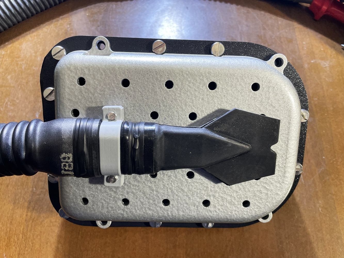
fig. 23 |
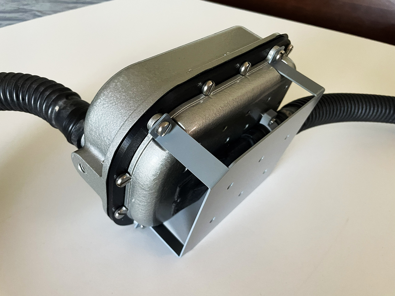
fig. 24 |
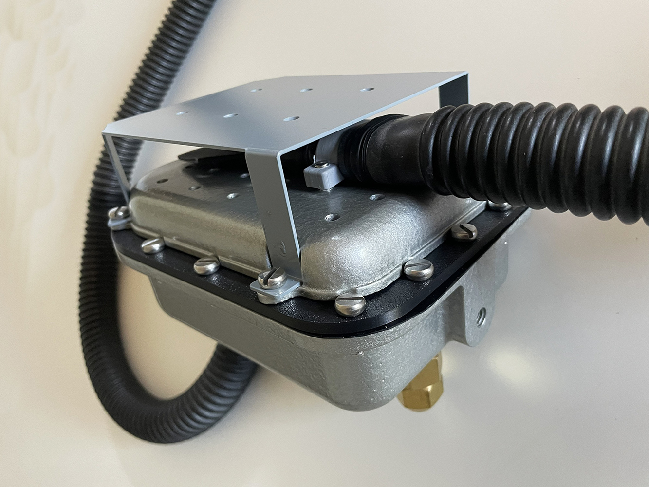
fig. 25 |
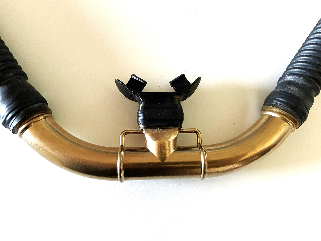
fig. 26 |
Regarding the corrugated hoses, which vary in length on the original unit due to the specific positioning of the second stage outlets, I used rubber hoses with a 25 mm (1-inch) internal diameter and a length of approximately 1 meter. These hoses, purchased online from a Ukrainian retailer, were trimmed to lengths as close as possible to those of the original unit (700 mm for the exhaust hose and 840 mm for the inhalation hose). The second stage, now complete and ready for final assembly onto the breathing apparatus, is shown in Figs. 27 and 28.
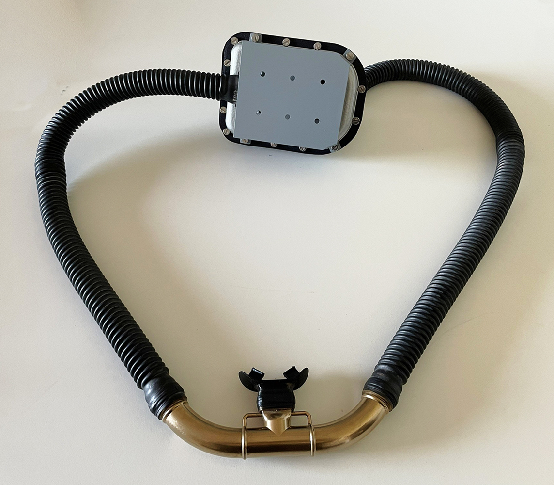
fig. 27 |
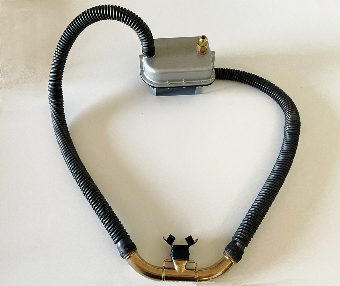
fig. 28 |
The first stage was also built using the same process described in my previously cited article, namely, starting with an old industrial pressure regulator very similar to the original manufactured by Air Liquide, which is unfortunately no longer available. Following the various machining steps and final painting, the component ready for installation on the replica is shown in Figs. 29 and 30. Note the safety pressure relief valve mounted on the regulator body; this was necessary when using "upstream" valves in second stages, such as the one installed in the Cousteau-Gagnan prototype breathing apparatus.
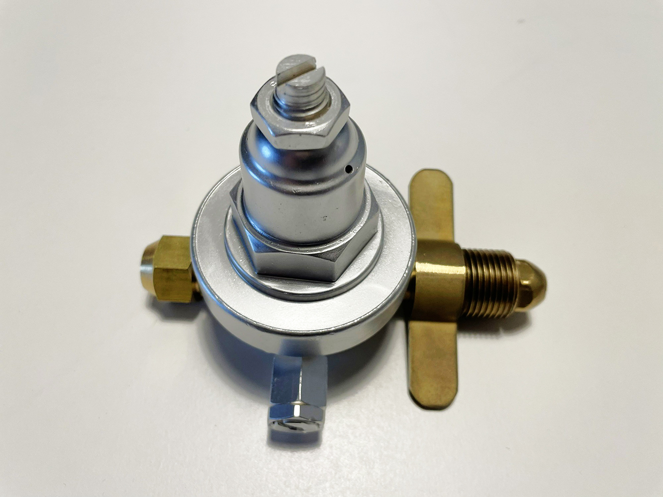
fig. 29 |
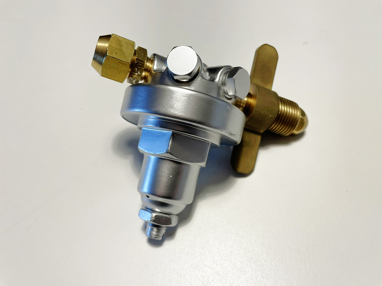
fig. 30 |
During the initial phase of the project, the components that caused me the most concern were the pneumatic circuit brass valves. In the original unit, these valves were used to refill the three cylinders and to switch between the primary and reserve systems. A total of three valves needed to be produced; apart from the knobs—which came in two different configurations—they appeared identical. The prospect of having to design and then build these components from scratch was hardly appealing, given the technical challenges and, above all, the high costs involved. I therefore searched online for commercially available valves that closely resembled the originals and could be modified for this purpose. After numerous unsuccessful attempts, I finally found what I was looking for. To my great surprise, I discovered that—more than 80 years after the original 1943 prototype was manufactured—these valves retained the key characteristics and main dimensions of the components from that time. Specifically, the dimensions and threading of the outlet port on the original valves (G5/8-14) were identical to those used today on scuba cylinder valves with DIN connections. The axial dimension of the outlet connections on these modern valves varies depending on the rated working pressure (200 bar or 300 bar). Off course, I chose the 200-bar valves, given that the working pressure of such units was almost always lower back then. The three valves purchased online for this project are shown in Figs. 31 and 32.
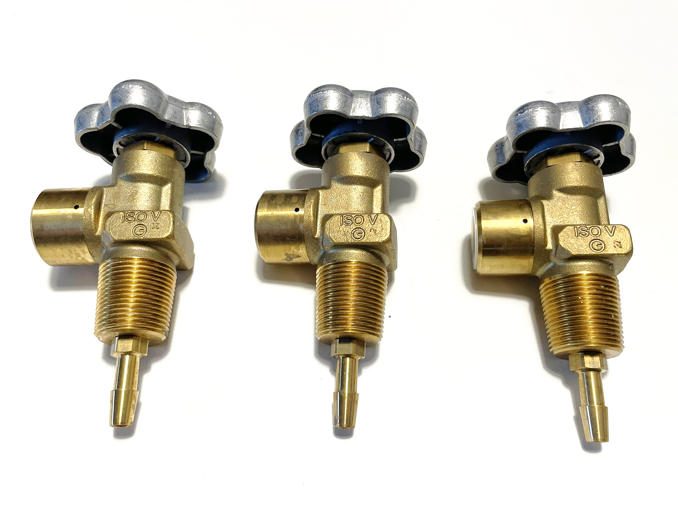
fig. 31 |
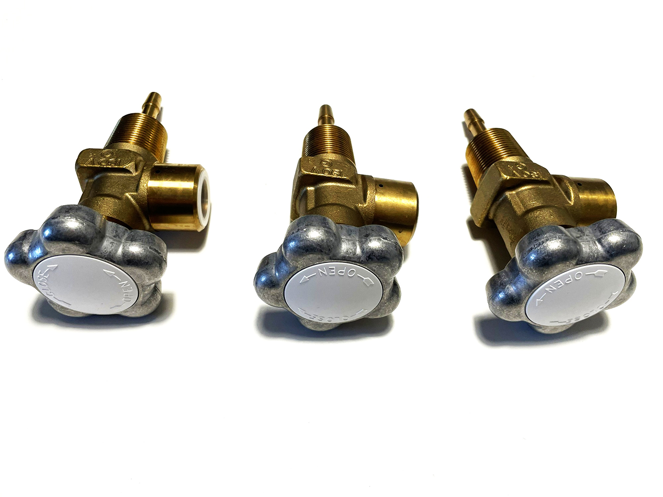
fig. 32 |
As can be seen from the previous photos, the adaptation work involved replacing the light-alloy knobs with ones specifically designed and manufactured to resemble the originals as closely as possible, and reworking the connecting stems that attach to the cylinders or to the copper piping.
The three valves are shown in Figs. 33 and 34 following the completion of the various reworking operations.
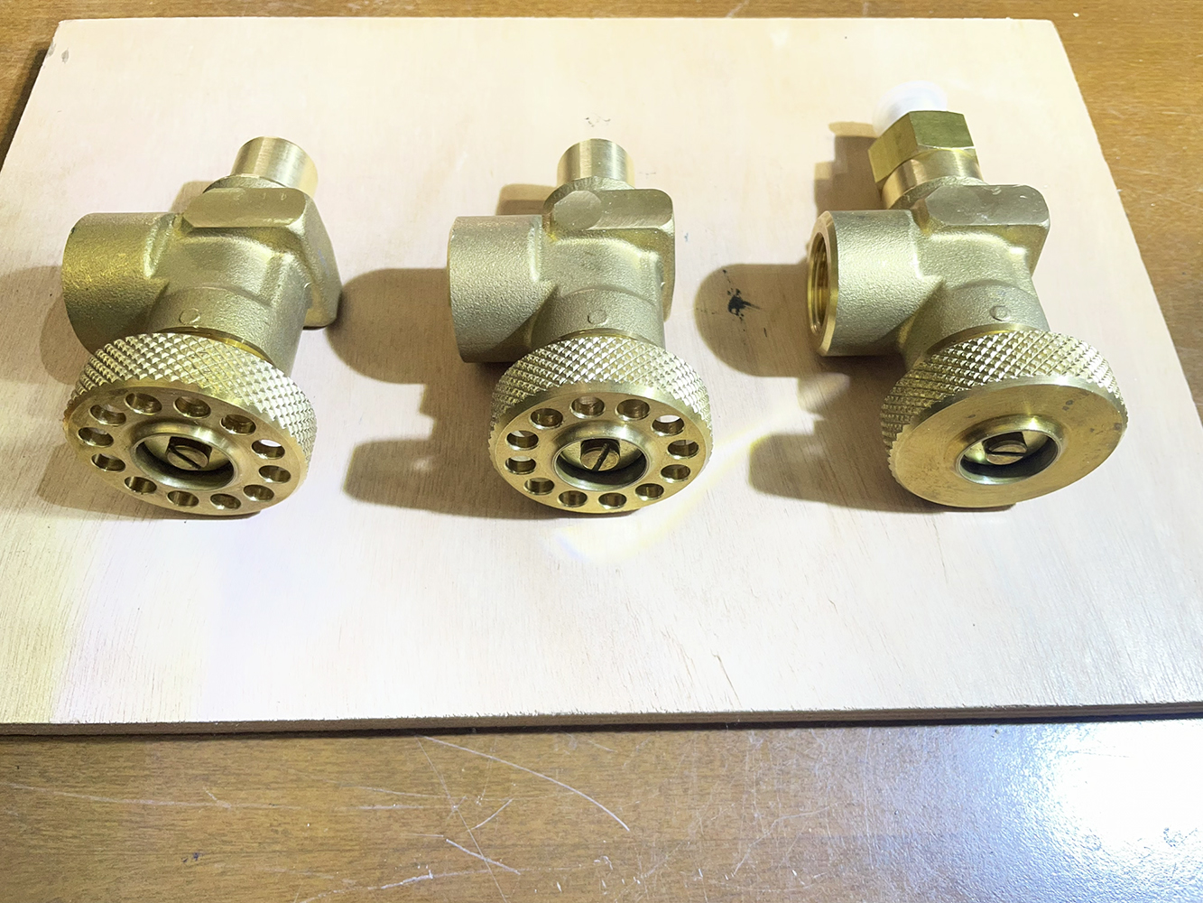
fig. 33 |
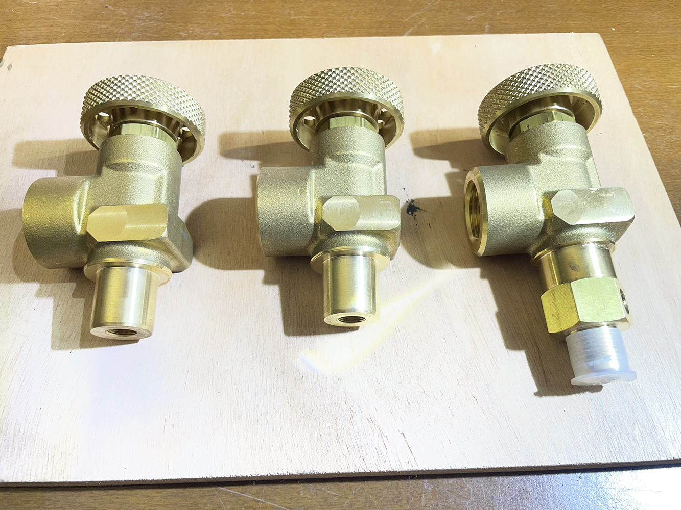
fig.34 |
As can be seen from the available photos, the two valves with perforated knobs are mounted and connected to each other using a specific brass adapter. The rigid pipe supplying the device's first stage will be connected to the center of this adapter. The resulting assembly is shown in Figs. 35 and 36.
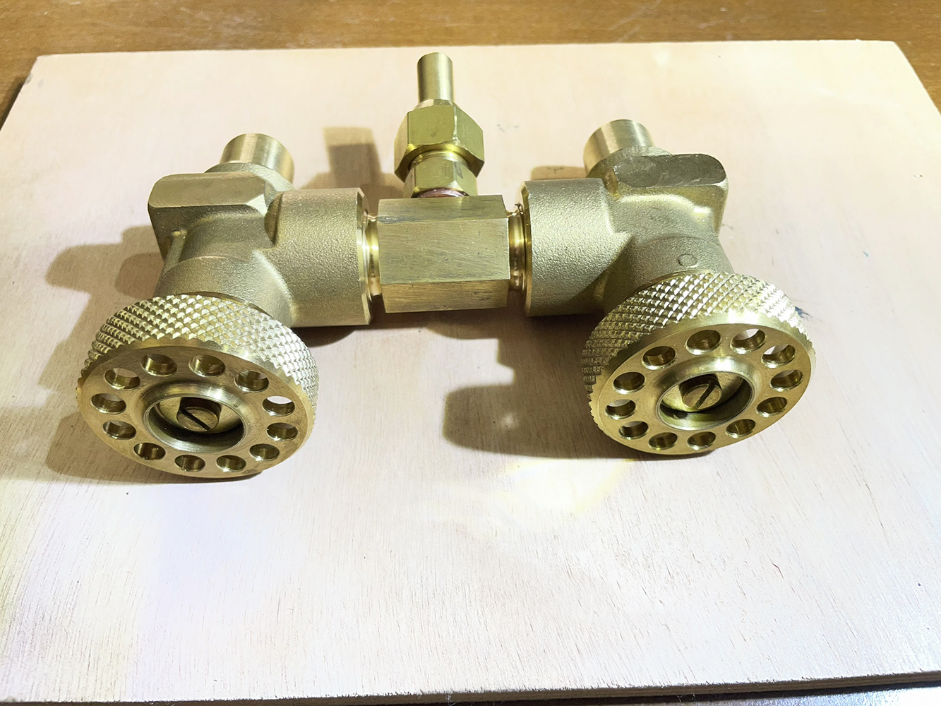
fig. 35 |
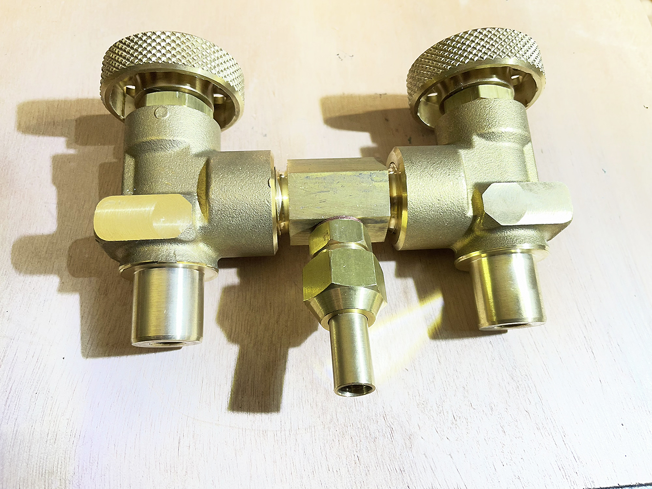
fig. 36 |
The two valves, assembled in this way, served to open and close the breathing apparatus's primary circuit (fed by the left and center cylinders, connected in parallel) and its reserve circuit (fed by the right cylinder).
The manufacturing of the rigid copper piping also required various feasibility analyses and a number of considerations. Ultimately, I decided to select copper tubing and brass fittings of the type used in air conditioning systems. This decision spared me the need to design and have a large number of components custom-manufactured in a workshop—a process that would have entailed prohibitive costs and challenges. The copper piping and key brass fittings selected and purchased online for this project are shown in Fig. 37. In addition to these materials, I also purchased the necessary tools for cutting, bending, and flaring the copper tubing (see Fig. 38).
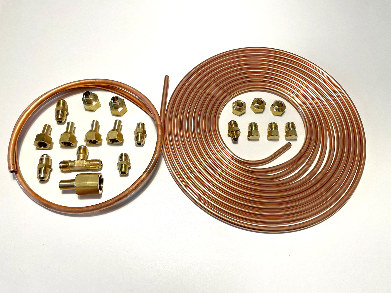
fig. 37 |
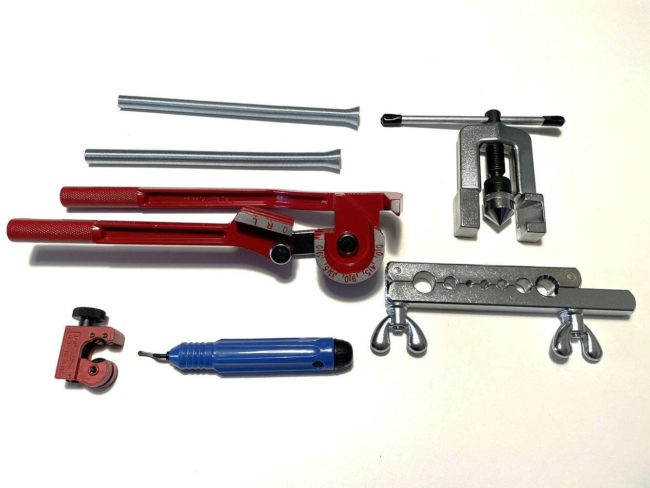
fig. 38 |
The copper tubing selected for this project consisted of 5/16-inch (7.93 mm) diameter pipes for all connections between cylinders and valves, and 3/8-inch (9.52 mm) diameter pipes for the connection between the first and second stages.
The selected tools allow for the manual cutting, bending, and flaring of the copper tubing to produce the piping required for the device's pneumatic circuit (see Figs. 39, 40, 41 and 42).
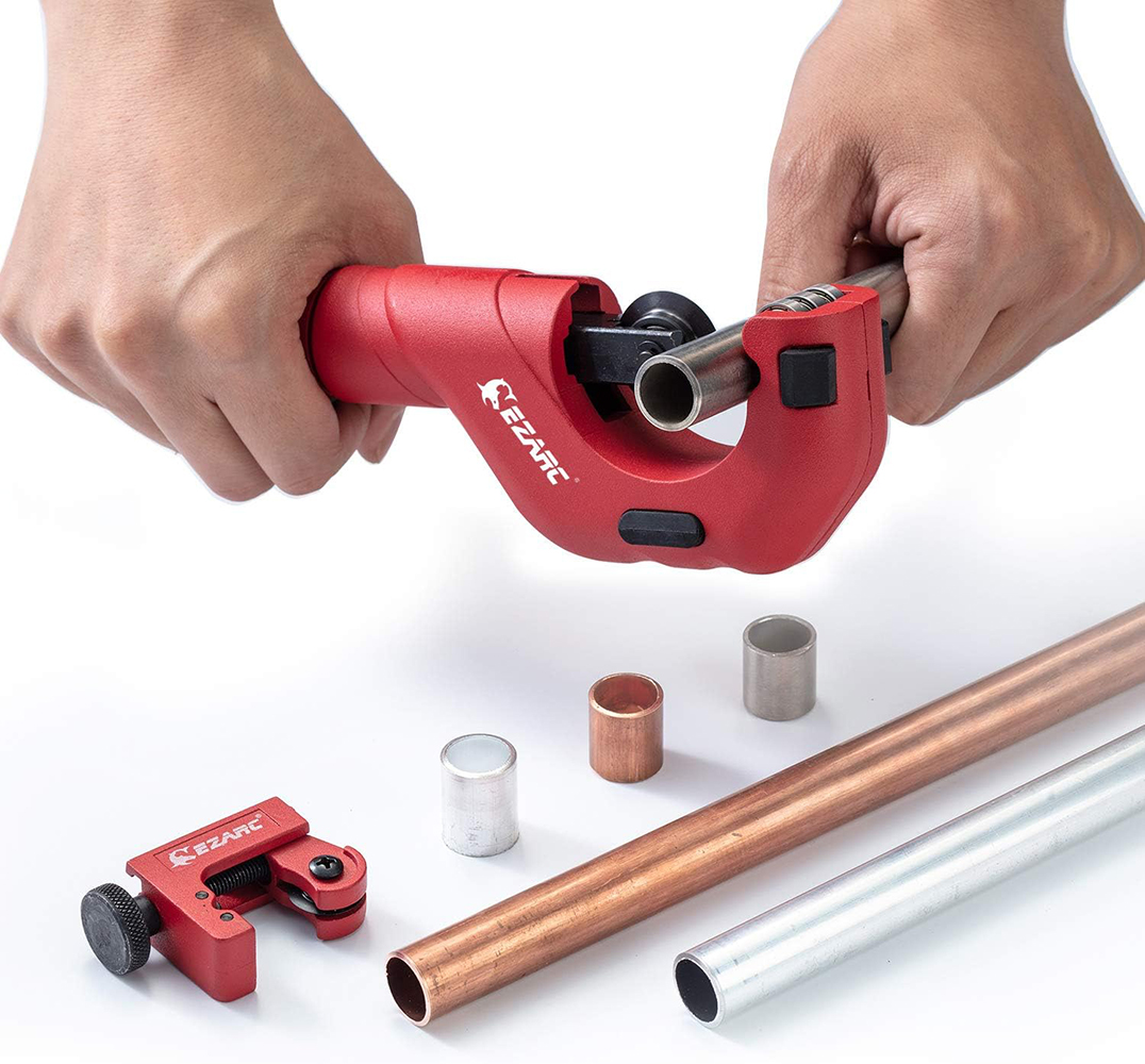
fig. 39 |
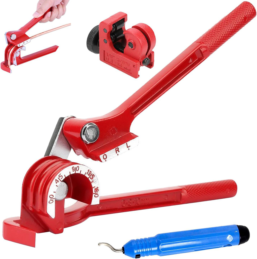
fig. 40 |
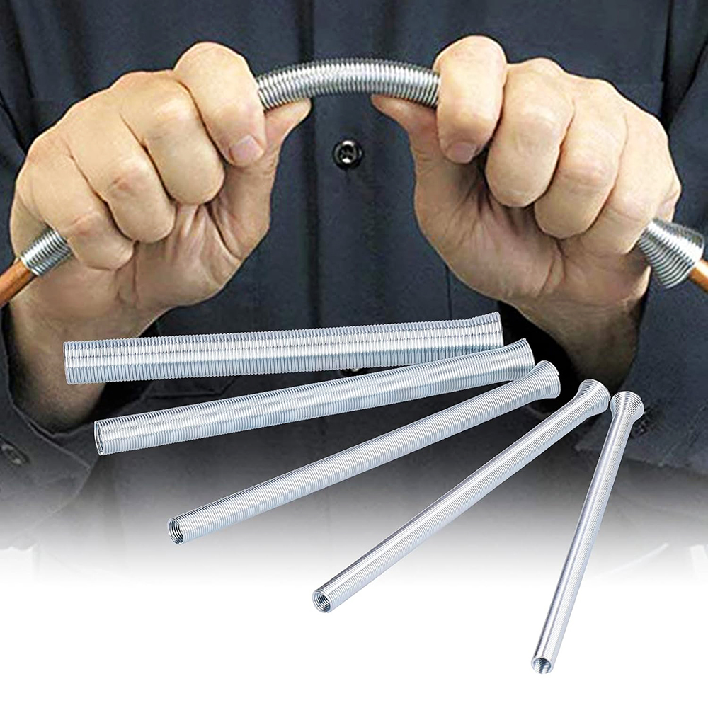
fig. 41 |
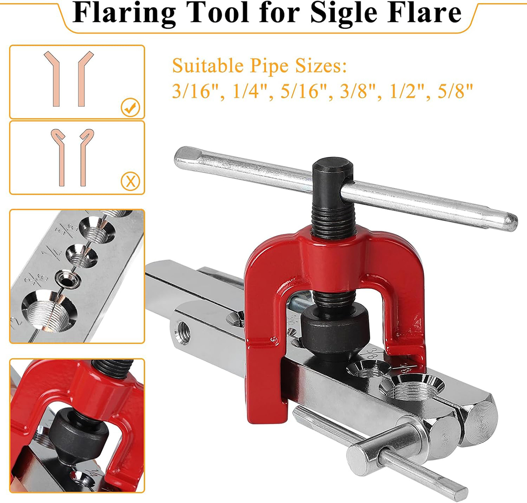
fig. 42 |
The only rigid pipe section for which I had to request the help of a workshop specializing in rigid pipe fabrication was the one connecting the first and second stages of the scuba unit. Its complex design made it impossible for me to fabricate the pipe manually using the equipment described above. Consequently, I first had to create a 3D design of the pipe (see Fig. 43) before proceeding with its fabrication in the workshop (see Fig. 44).
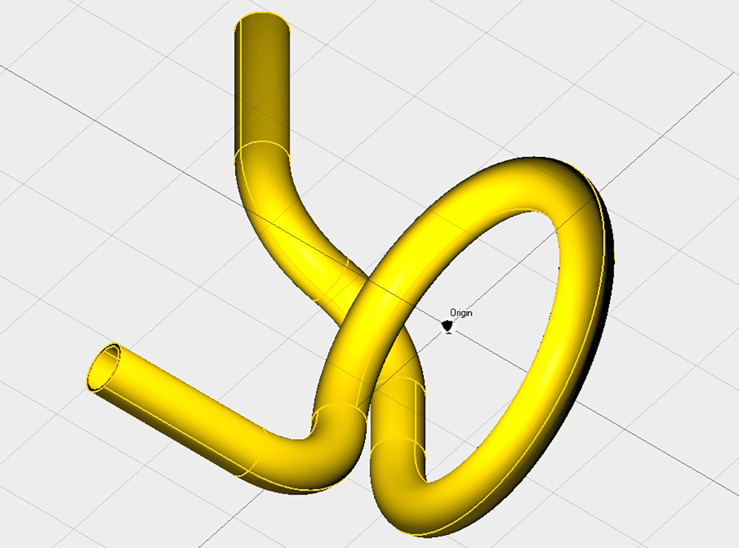
fig. 43 |
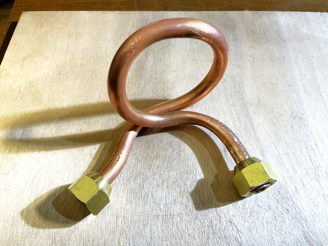
fig. 44 |
As with the unit at the Dumas Museum, the breathing apparatus harness was manufactured using black leather straps (see Fig. 45). Measurements taken from available photos indicated the need to purchase 5 cm-wide leather strips for the shoulder straps and waist belt, and 7 cm-wide strips for the backplate support surface. Other essential components for the harness assembly were double-prong brass buckles. Examination of the photos revealed that the waist belt buckle differed significantly from those used on the shoulder straps. After extensive online research, buckles closely resembling the originals were identified and purchased (see Figs. 46 and 47). The materials acquired for the harness and the main tools used for the various stages of construction are shown in Fig. 48.
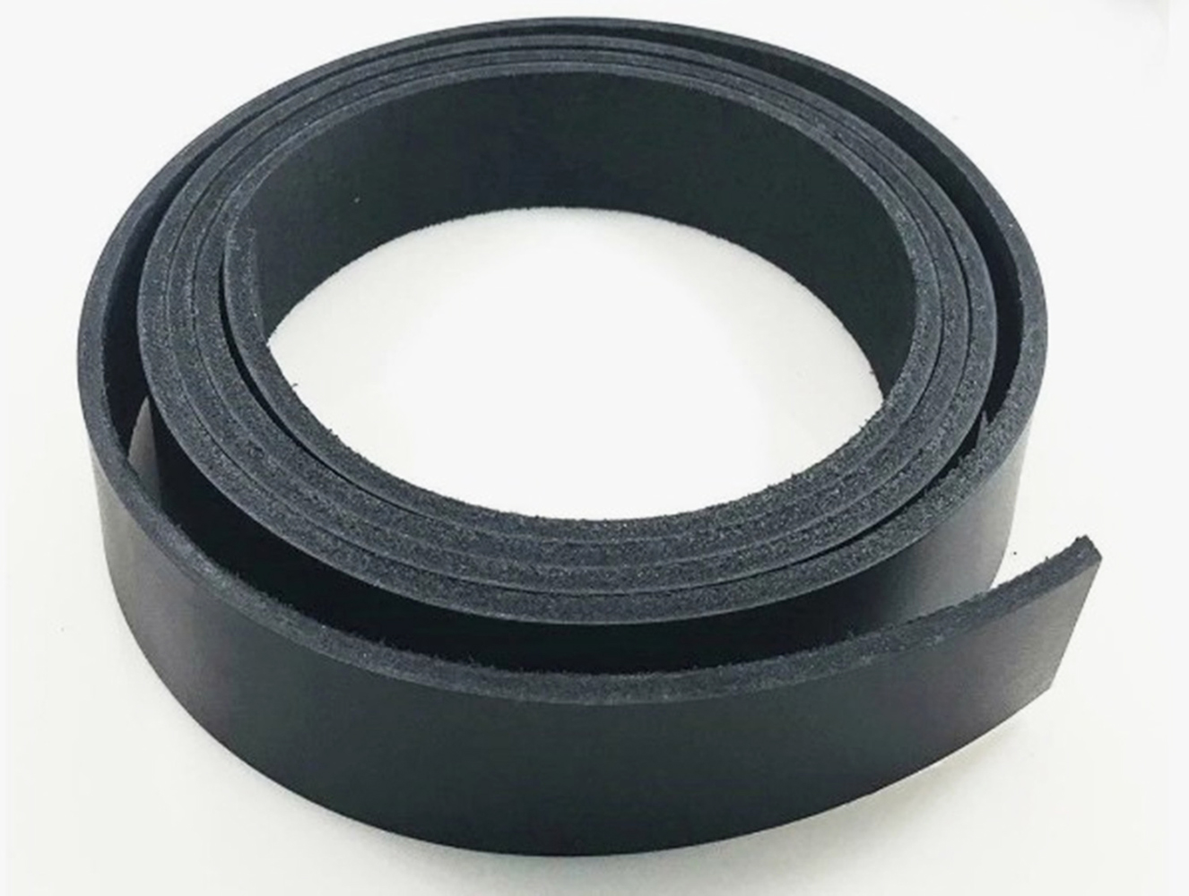
fig. 45 |
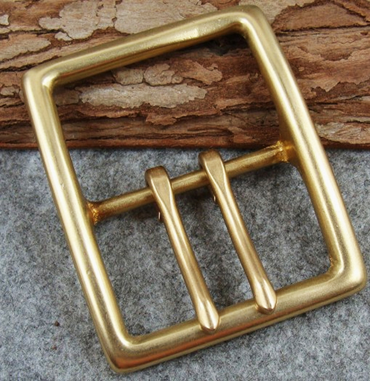
fig. 46 |
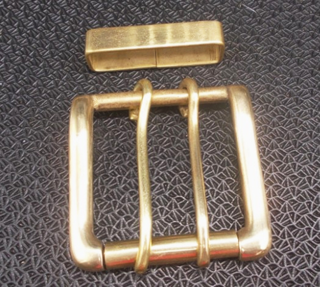
fig. 47 |
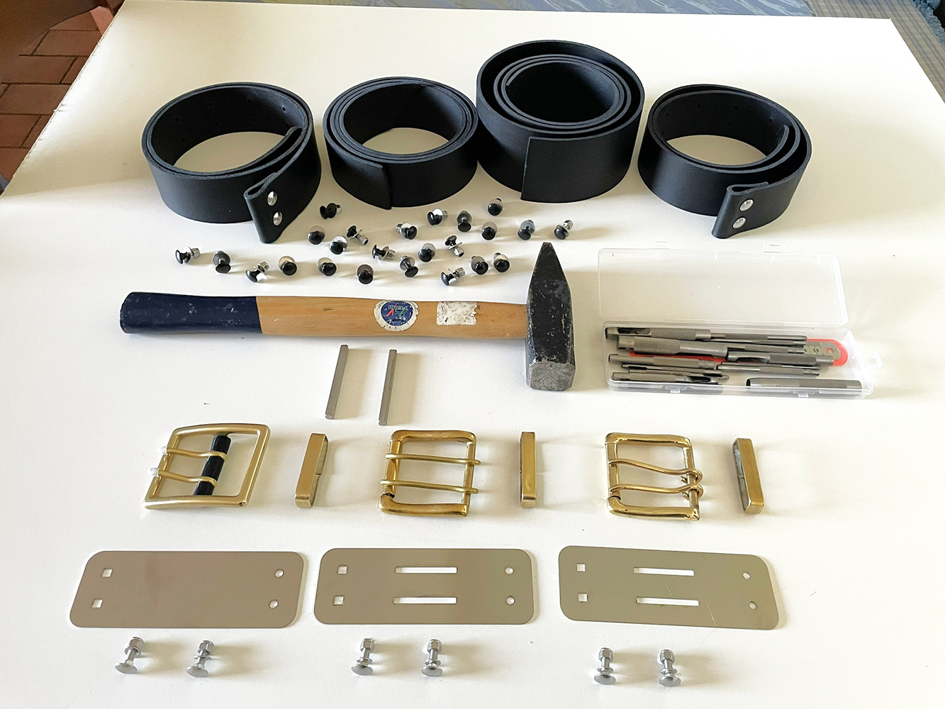
fig. 48 |
To connect the double-prong buckles to the leather straps, special stainless-steel plates were designed and manufactured (see Fig. 48); these were then folded 180° at their midpoint and finally secured to the straps using special M5 bolts featuring a square shank section and a hemispherical head (see Figs. 49 and 50).
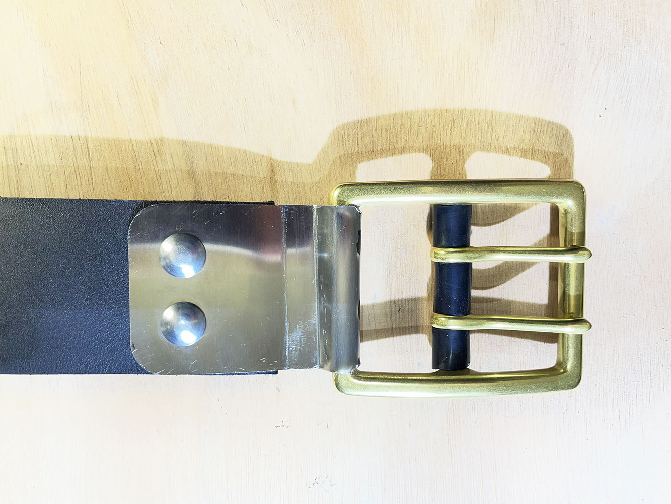
fig. 49 |
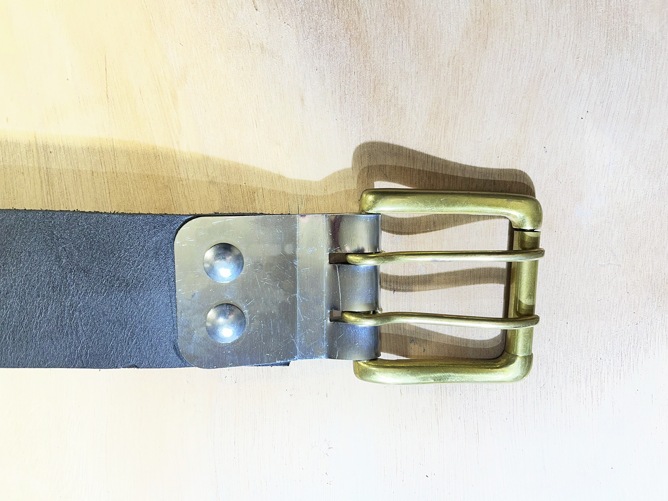
fig. 50 |
Finally, several other secondary components were identified and purchased online prior to the start of the replica’s final assembly phase. Examples include stainless steel U-bolts (27 mm internal diameter, M6 thread) used to secure the cylinder end cap necks to the frame (see Fig. 51); copper strip (10 mm wide, 1 mm thick) used to fabricate clamps and brackets for attaching the copper piping to the frame (see Fig. 52); aluminum strip (20 mm wide, 1 mm thick) used to manufacture brackets for attaching the second stage to the frame (see Fig. 53); and special M8 hex-socket button-head bolts used to connect the second stage to the aforementioned brackets (see Fig. 54).
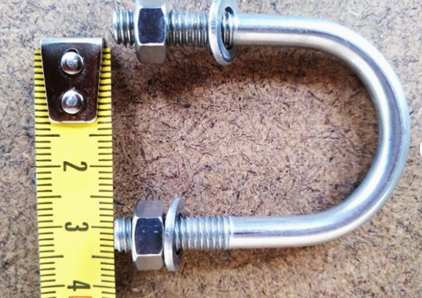
fig. 51 |
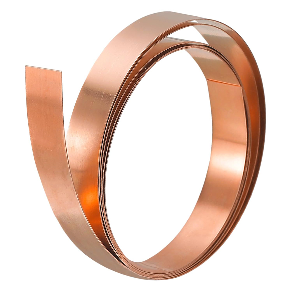
fig. 52 |
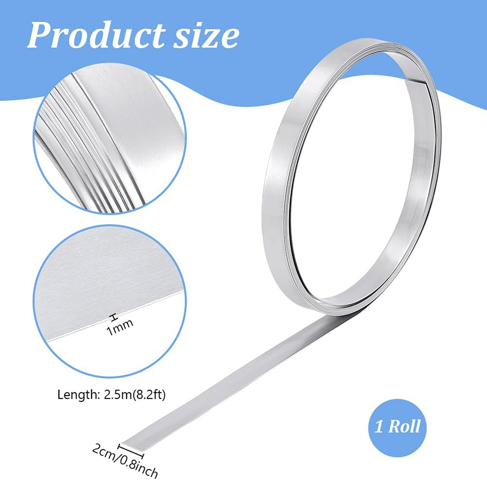
fig. 53 |
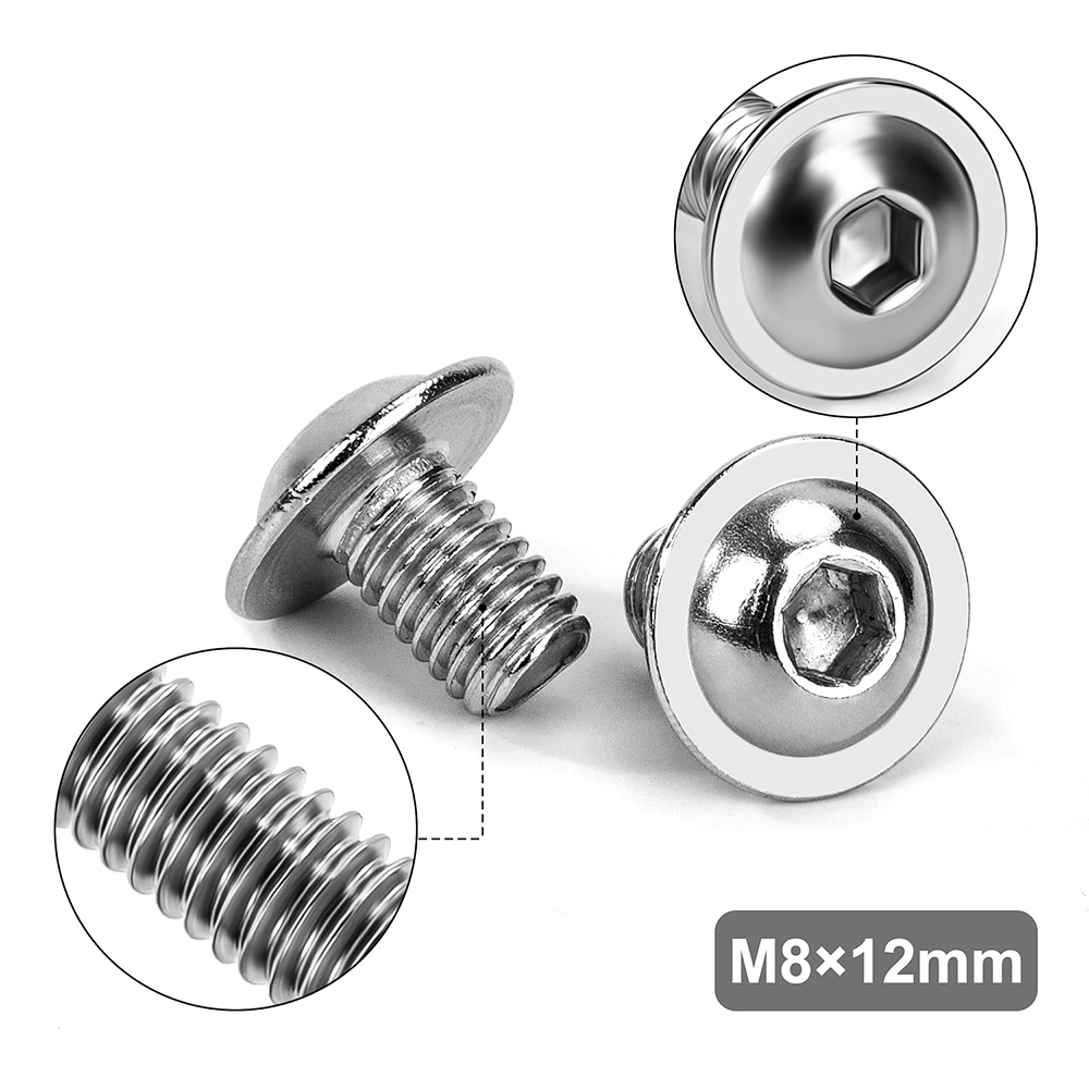
fig. 54 |
The final assembly of the replica required great care to accurately replicate the configuration of the original prototype and to avoid damaging the various components; ultimately, however, the replica was completed and mounted on a black torso-style mannequin. This type of mannequin is the standard chosen for displaying many other historical breathing sets of my small museum in Gubbio. For improved stability and visibility, the entire assembly was mounted and secured onto a dedicated black wooden base (see Figs. 55, 56, 57, 58, 59, 60, 61, 62, 63 and 64).
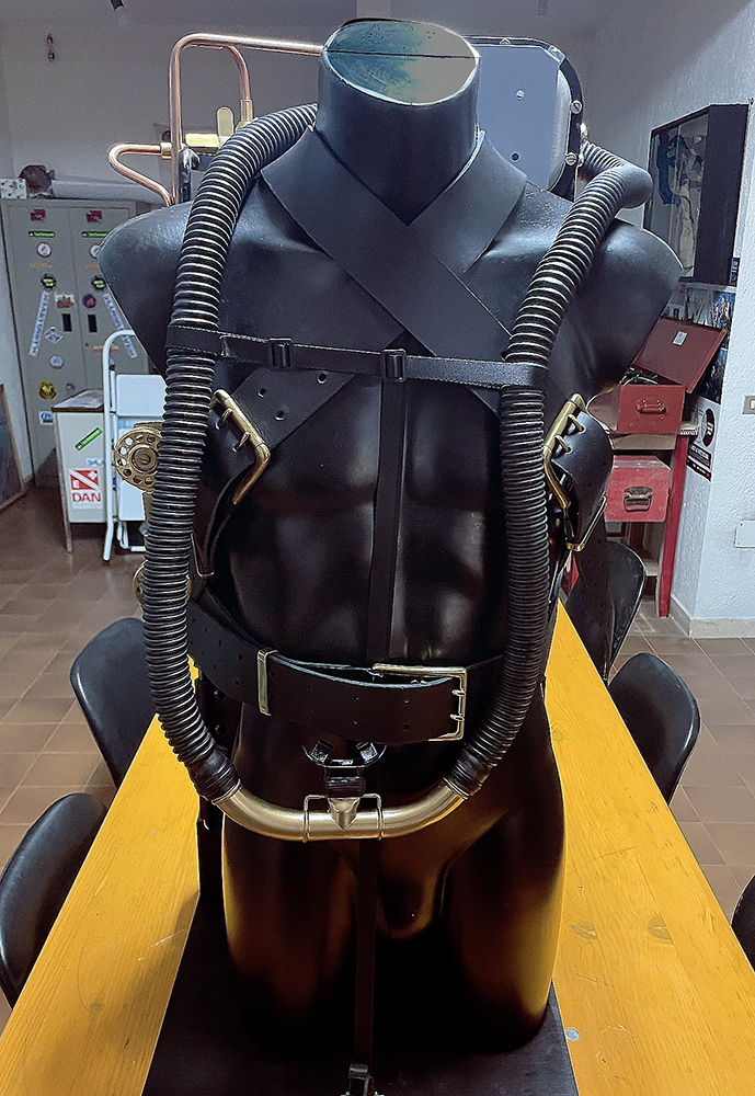
fig. 55 |
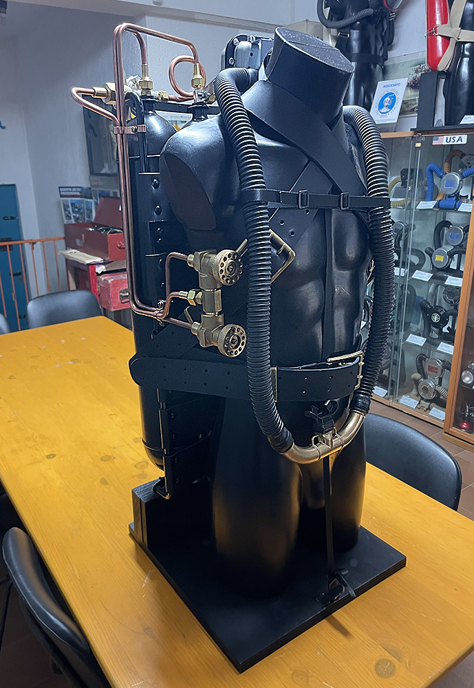
fig. 56 |
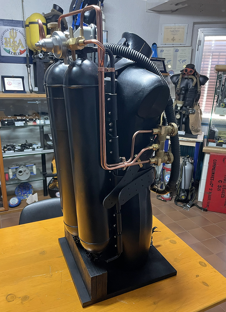
fig. 57 |
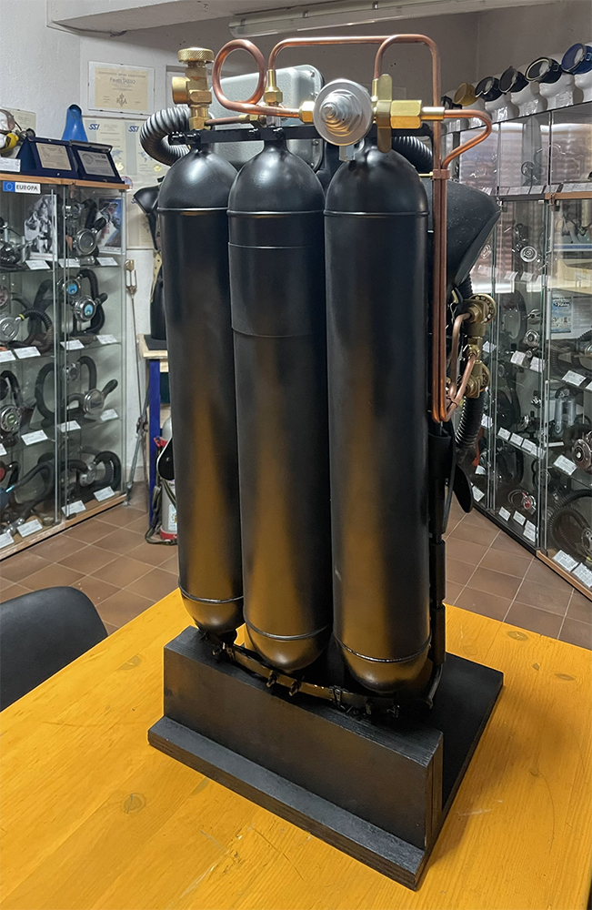
fig. 58 |
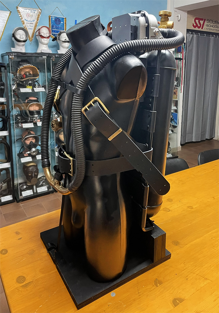
fig. 59 |
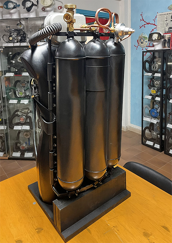
fig. 60 |
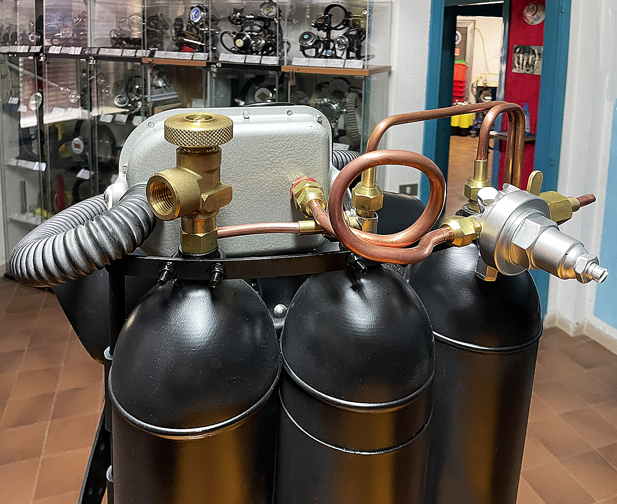
fig. 61 |
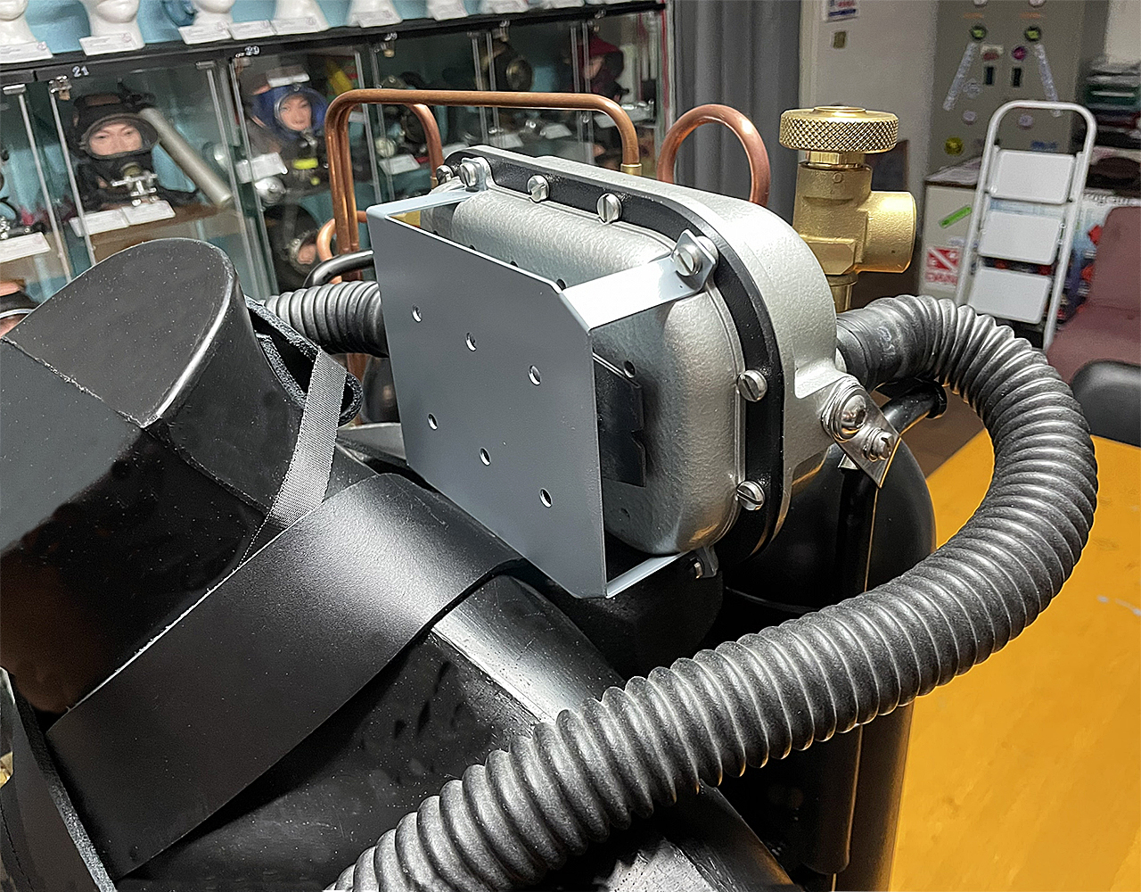
fig. 62 |
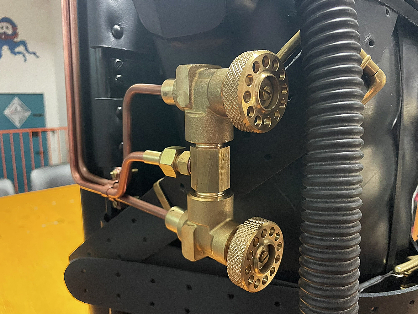
fig. 63 |
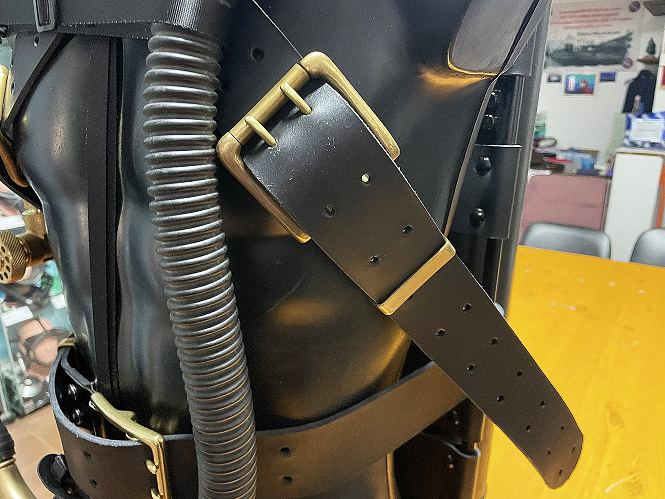
fig. 64 |
Comparing the replica I have built with photos of the original prototype on display at the Dumas Museum leads me to believe that the result is satisfactory and fully meets my initial expectations. Now, I hope that the nagging voice in my head stops tormenting me about what it deems unfinished, and that my conscience can finally regard this long, challenging, yet stimulating adventure, dedicated to reconstructing the Cousteau-Gagnan breathing apparatus prototypes, as truly complete. From now on, I can finally devote my attention and energy as a collector and restorer to other restoration and reconstruction projects. I hope these will be also stimulating as the previous ones.
_______________